
System and apparatus for axial field rotary energy device

a technology of axial field and energy device, which is applied in the direction of magnetic circuit rotating parts, magnetic circuit shape/form/construction, windings, etc., can solve the problems of large motor size, difficult manufacturing, and relatively high cos

Active Publication Date: 2018-11-08
INFINITUM ELECTRIC INC
View PDF0 Cites 9 Cited by
  • Summary
  • Abstract
  • Description
  • Claims
  • Application Information

AI Technical Summary

Benefits of technology

The patent describes an axial field rotary energy device that includes a stator assembly and a rotor assembly. The stator assembly has multiple stator panels that are stacked together and each contains a printed circuit board with coils that are interconnected. This creates a single electrical phase. The rotor assembly has multiple rotors that are coupled together and each rotor contains magnets with specific distances between them. The device can generate electricity when the rotor assembly rotates. The technical effects of this design include improved electrical performance and efficiency, reduced size and weight, and improved mechanical performance.

Problems solved by technology

Such motors are relatively large and difficult to manufacture.
However, some of these designs are complicated, relatively expensive and they are not modular.

Method used


Image

  • System and apparatus for axial field rotary energy device
  • System and apparatus for axial field rotary energy device
  • System and apparatus for axial field rotary energy device

Examples


Embodiment Construction

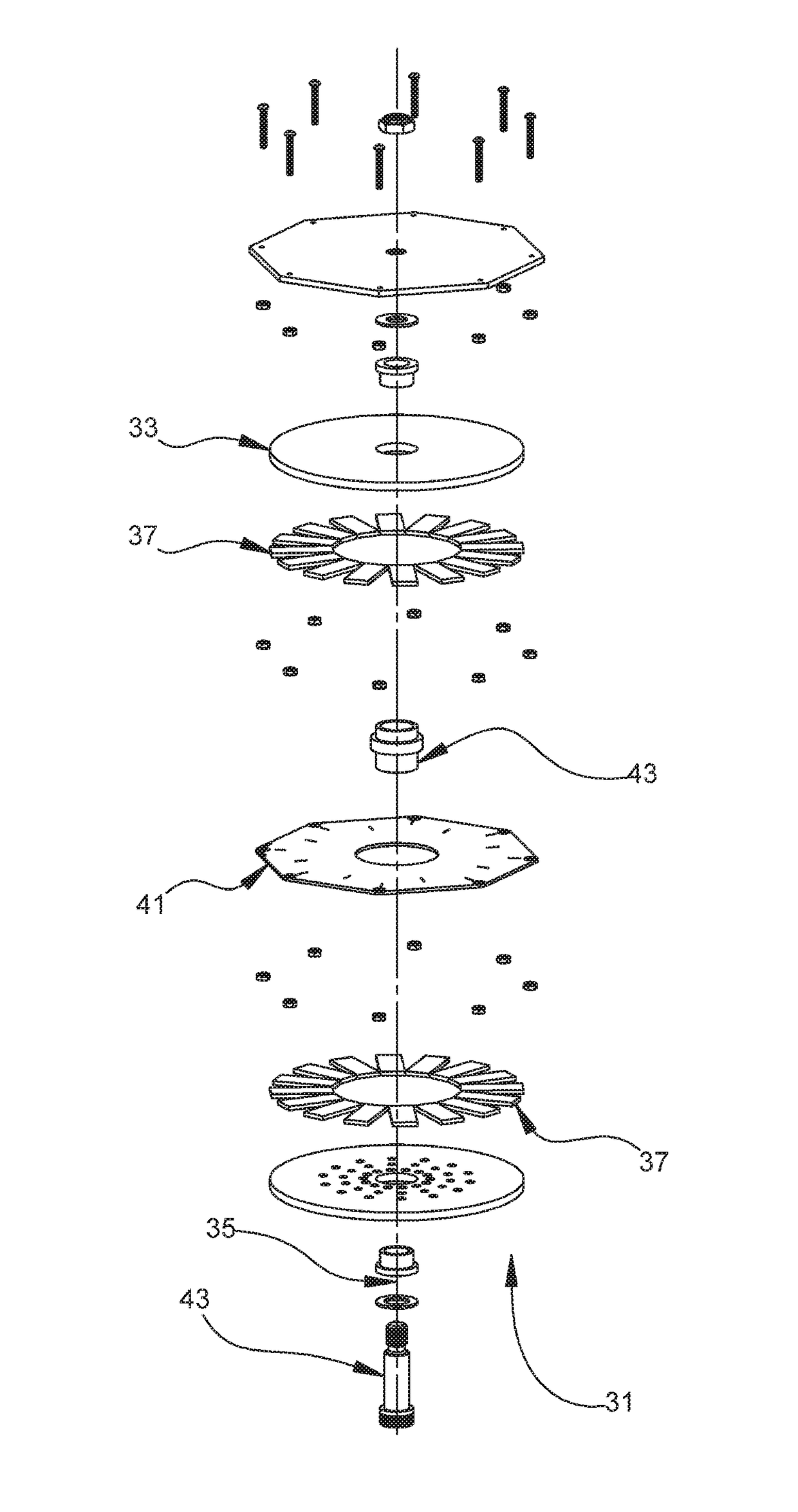
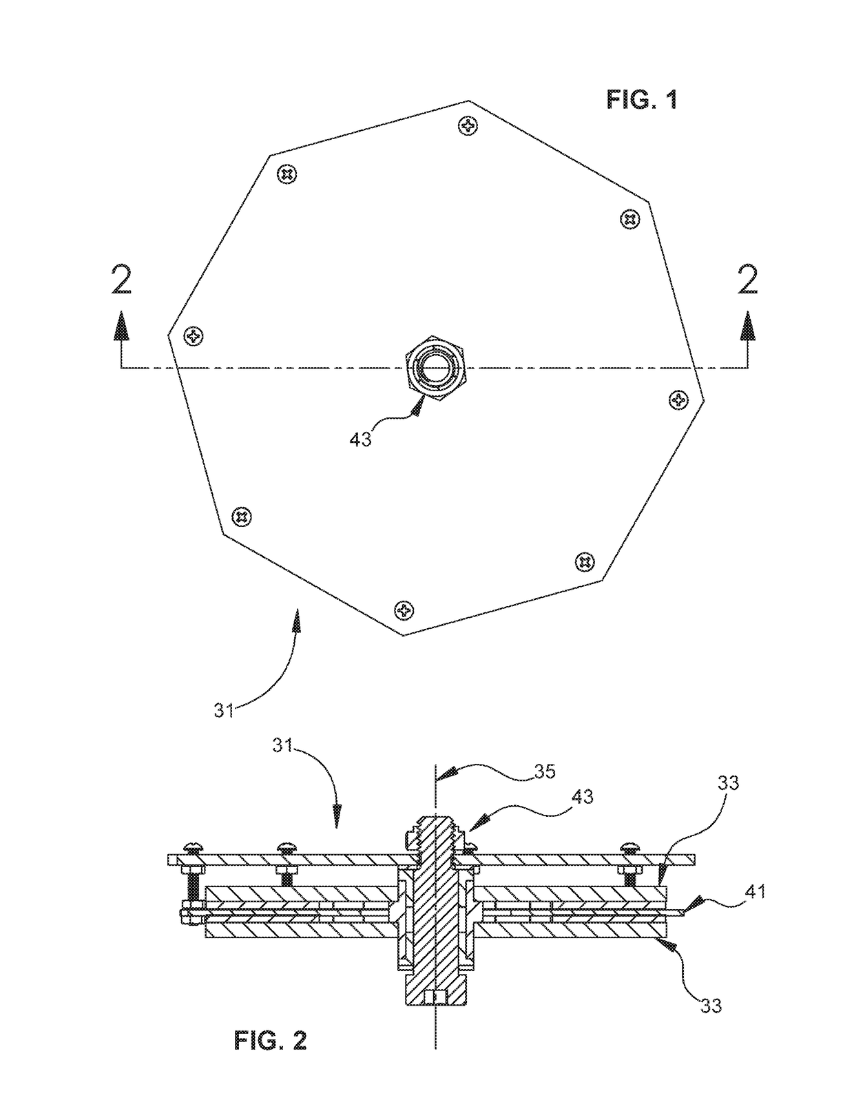
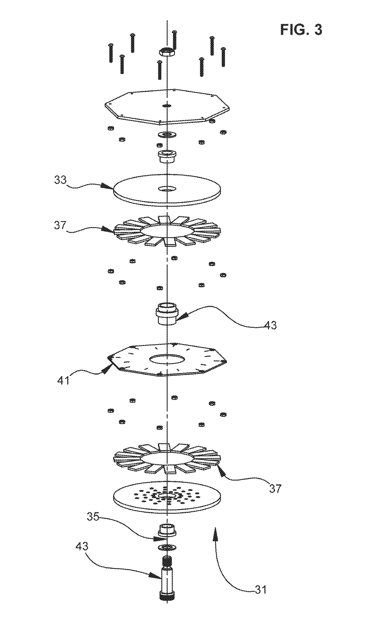
[0057]FIGS. 1-3 depict various views of an embodiment of a device 31 comprising an axial field rotary energy device (AFRED). Depending on the application, device 31 can comprise a motor that converts electrical energy to mechanical power, or a generator that converts mechanical power to electrical energy.

[0058]I. Panels

[0059]Embodiments of device 31 can include at least one rotor 33 comprising an axis 35 of rotation and a magnet (i.e., at least one magnet 37). A plurality of magnets 37 are shown in the embodiment of FIG. 3. Each magnet 37 can include at least one magnet pole. The magnets 37 can comprise various shapes, such as trapezoidal, conical, etc.

[0060]Device 31 also can include a stator 41 that is coaxial with the rotor 33. Rotor 33 can be coupled on a shaft 43 and with other hardware, such as one or more of the following items: a mount plate, fastener, washer, bearing, spacer or alignment element. Embodiments of the stator 41 can include a single unitary panel, such as the p...


PUM


Abstract

An axial field rotary energy device can include a housing having an axis. A stator assembly is mounted to the housing and has stator panels that are axially-stacked and discrete panels from each other. Each stator panel includes a respective printed circuit board (PCB) having respective coils that are electrically conductive and interconnected within the respective PCB. In addition, a rotor assembly including rotors is rotatably mounted within the housing on opposite axial ends of the stator assembly. The rotors can be mechanically coupled together. Each rotor can include magnets having leading and trailing edges. The trailing edge of one magnet and the leading edge of an adjacent magnet can be parallel to each other to define a consistent circumferential spacing, relative to the axis, between adjacent ones of the magnets.

Description

[0001]This application is a continuation-in-part of and claims priority to and the benefit of U.S. application Ser. No. 15 / 935,883, filed Mar. 26, 2018, which is a continuation-in-part of and claims priority to and the benefit of U.S. application Ser. No. 15 / 864,663, filed Jan. 8, 2018, which claims priority to and the benefit of U.S. Prov. App. No. 62 / 609,900, filed Dec. 22, 2017, U.S. Prov. App. No. 62 / 457,696, filed Feb. 10, 2017, U.S. Prov. App. No. 62 / 445,289, filed Jan. 12, 2017, U.S. Prov. App. No. 62 / 445,211, filed Jan. 11, 2017, and U.S. Prov. App. No. 62 / 445,091, filed Jan. 11, 2017, each of which is incorporated herein by reference in its entirety.BACKGROUND OF THE INVENTIONField of the Disclosure[0002]The present invention relates in general to an axial field rotary energy device and, in particular, to a system, method and apparatus for modular motors and generators having one or more printed circuit board (PCB) stators.Description of the Prior Art[0003]Conventional, axi...

Claims


Application Information

Patent Timeline
IPC IPC(8): H02K16/02H02K1/18H02K1/27H02K3/26H02K3/28H02K21/24H02K11/30
CPCH02K16/02H02K1/182H02K1/2793H02K3/26H02K3/28H02K21/24H02K11/30H02K2203/03H02K5/04H02K5/1732H02K16/00H02K2213/03H02K1/2798
Inventor SCHULER, BERNHARD L.LEE, RICHRASMUSSEN, JORGEN
Owner INFINITUM ELECTRIC INC
Learn More