Ultrasonic humidifier with a central atomizing tube

a technology of atomization tube and humidifier, which is applied in the direction of lighting and heating apparatus, heating types, domestic applications, etc., can solve the problems of reducing the misting effect and the amount of mist, the humidifier cannot effectively produce water mist, and the transducer cannot make a large amount of water above to produce considerable amplitude, etc., to achieve good reliability, simple use, and easy cleaning

Inactive Publication Date: 2018-11-15
WANG ZHIJING
View PDF10 Cites 7 Cited by
  • Summary
  • Abstract
  • Description
  • Claims
  • Application Information

AI Technical Summary

Benefits of technology

[0005]The purpose of this invention is to overcome the technical shortcomings of the existing ultrasonic humidifier with top fill water tank, and to provide an ultrasonic humidifier which is simple to use, easy to clean, has good reliability and misting performance.

Problems solved by technology

If the height of the water increases, due to the transducer's oscillation energy is limited, the transducer cannot make a large amount of water above to produce considerable amplitude.
So the humidifier cannot effectively produce water mist, greatly reducing the misting effect and the amount of mist.
Therefore the water tank is difficult to clean, its internal is easy to produce mold, bacteria and cause other issues.
The use the conventional humidifiers are of inconvenient and unsanitary.
In addition the design is also complex with high manufacturing costs.
Due to the pump, the reliability and service life of the humidifiers are greatly affected.
It also increases noise.
The additional pump also increases the cost.

Method used


Image

  • Ultrasonic humidifier with a central atomizing tube
  • Ultrasonic humidifier with a central atomizing tube
  • Ultrasonic humidifier with a central atomizing tube

Examples


Embodiment Construction

[0016]The invention will be described further below with reference to the accompanying drawings.

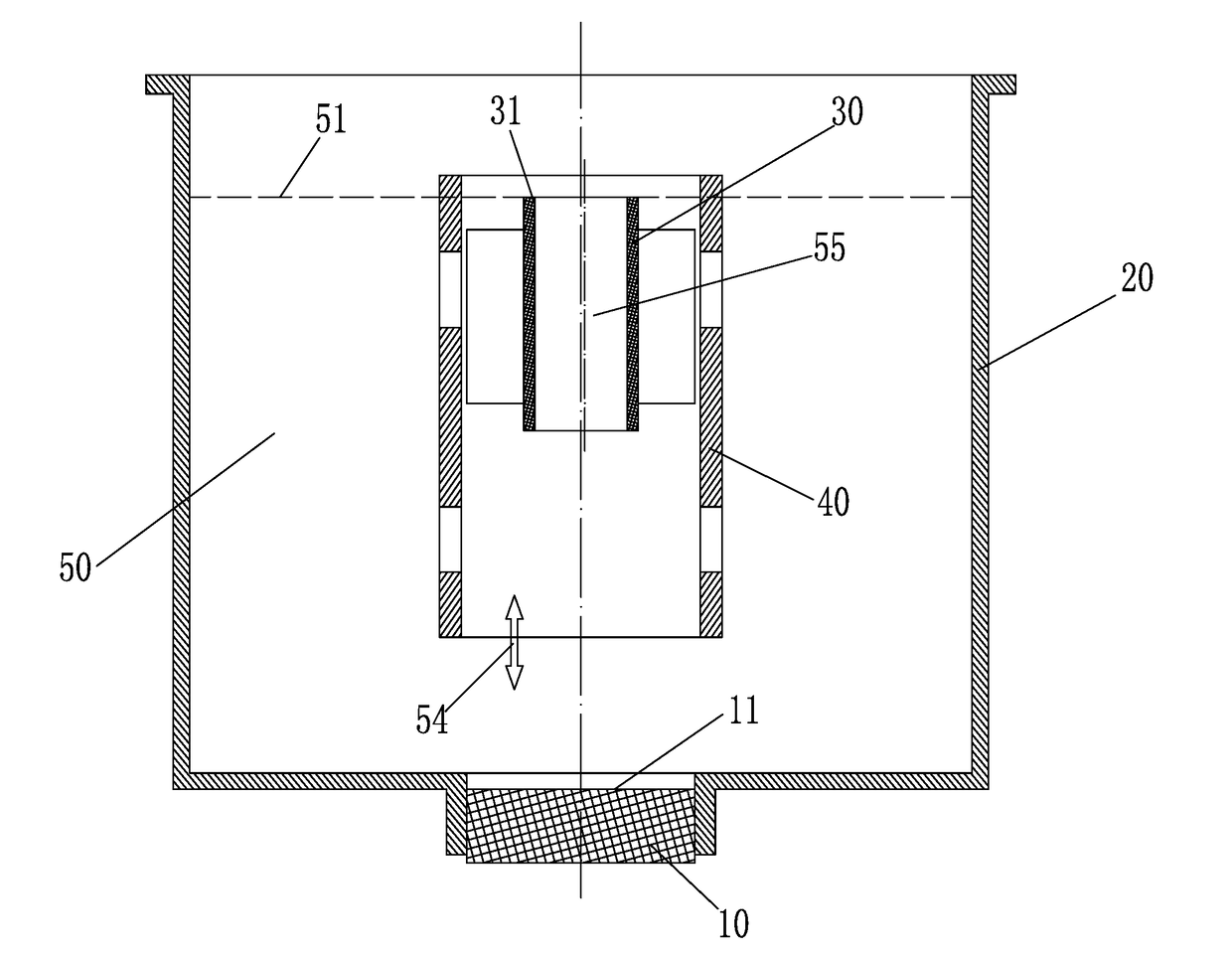
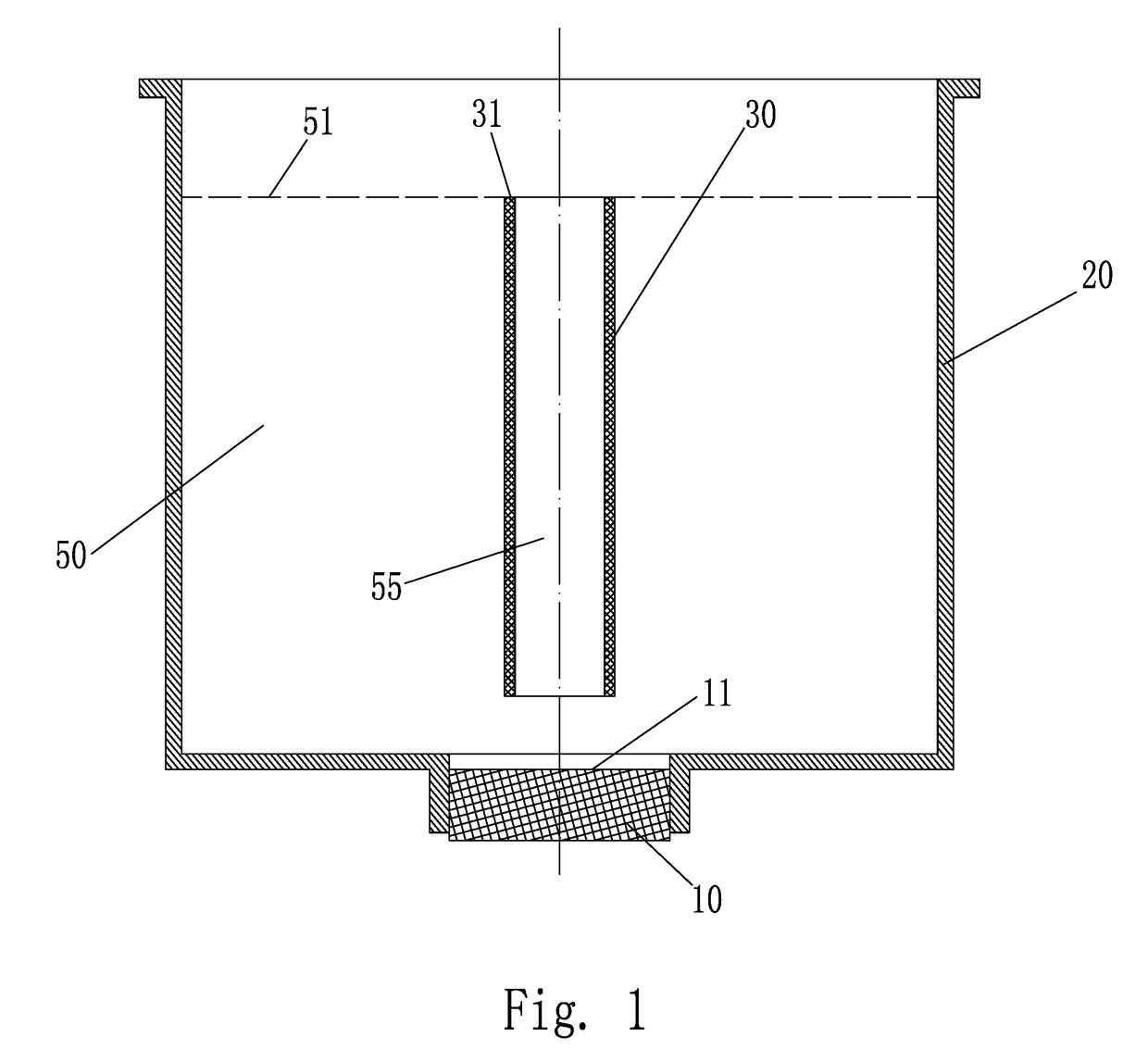
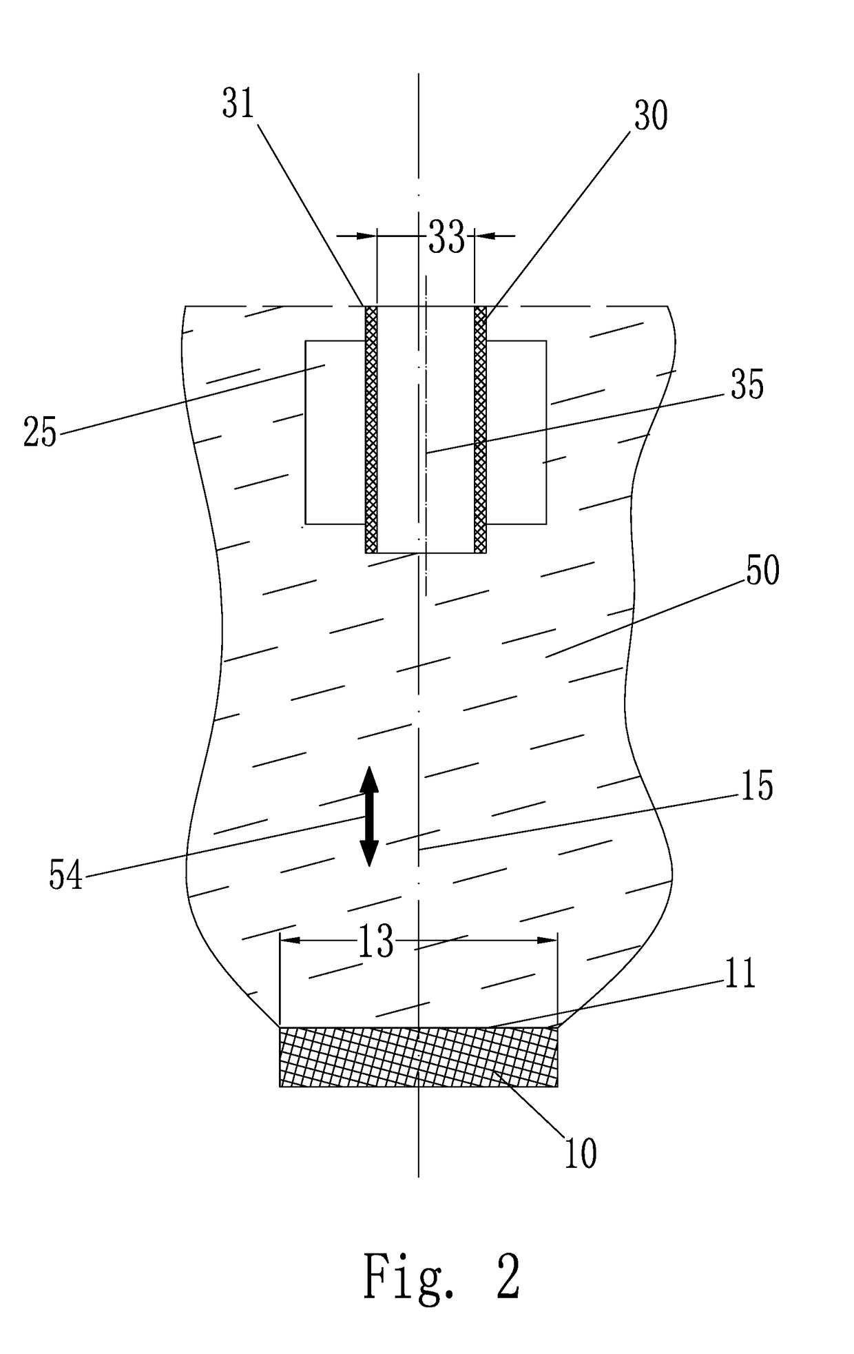
[0017]The ultrasonic humidifier with a central atomizing tube as shown in FIGS. 1 to 2 includes an oscillating transducer 10 which can cause ultrasonic vibration of the water 55 above it, an open top water tank 20 for maintaining the water 50 above the transducer, and a central atomizing tube 30 separating the central oscillating water column 55 from the peripheral water 50 from water surface to a certain distance below. The vibrating surface 11 of the ultrasonic oscillating transducer 10 can vibrate in a direction perpendicular to its surface, causing the water above the transducer to vibrate in the direction 54 perpendicular to the transducer surface 11. The central atomizing tube 30 is rigid body. Its function is to isolate the central oscillating water column 55 from the peripheral water 50 and the oscillation of the central oscillating water column 55 is not or less affected by the s...


PUM


Abstract

An ultrasonic humidifier is comprised of an oscillating transducer which can emit ultrasonic waves to the water above it, an open water container which maintain the water level above the transducer, a central atomizing tube, which separates the central vibrating water column from the water around it, on the water surface to certain distance below, and a guide mechanism for maintaining a corresponding position between the center atomizing tube and the transducer. The central atomizing tube needs to keep its centerline coincide with the centerline of the oscillating water column generated by the transducer. The upper end of the central atomizing tube is flush with the water surface, so that the mist generating performance is kept basically stable regardless changing height of the water level. The central atomizing tube may be fitted with an end face or side structure to cooperate with the guide mechanism or other mechanism to achieve the above functional and performance requirements. An ultrasonic humidifier with a central atomizing tube can have increased mist performance by adding a separation tube, which separates a water column from surrounding water.

Description

FIELD OF THE INVENTION[0001]The invention relates to an ultrasonic humidifier with a central atomization tube, which is used to keep humidifier mist performance stable regardless water level.BACKGROUND OF THE INVENTION[0002]Ultrasonic humidifiers generally have a transducer that oscillates the water, a water reservoir with a fixed water level, and a water tank with a closed top end. The outlet of the tank is flush with the water at the bottom of the tank, and the vacuum in the tank keeps the water from running out. When the water level drops during use, the air gets into the tank from the tank outlet. This design achieves a controlled discharge of water, so that the water surface is highly stable. This design is based on maintaining the same height of the water level, in order to make the humidifier generate the mist normally and keep the mist amount stable. If the height of the water increases, due to the transducer's oscillation energy is limited, the transducer cannot make a larg...

Claims


Application Information

Patent Timeline
Patent Type & Authority Applications(United States)
IPC IPC(8): B05B17/06F24F6/12B05B7/00
CPCB05B17/0615B05B17/0653B05B7/0012F24F6/12
Inventor WANG, ZHIJING
Owner WANG ZHIJING
Why Eureka
Try Eureka