On-vehicle apparatus, alert output method, and computer readable medium
a technology of alert output and vehicle, applied in the field of vehicle equipment, can solve problems such as collisions between adjacent vehicles and vehicles, and achieve the effect of reducing the risk of collisions
- Summary
- Abstract
- Description
- Claims
- Application Information
AI Technical Summary
Benefits of technology
Problems solved by technology
Method used
Image
Examples
first embodiment
[0022]Description of Configuration
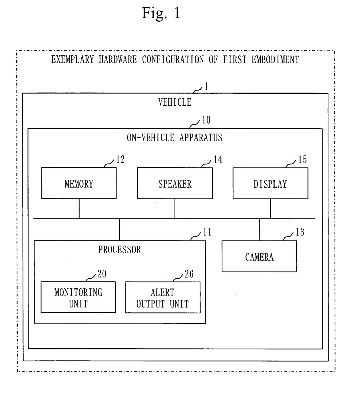
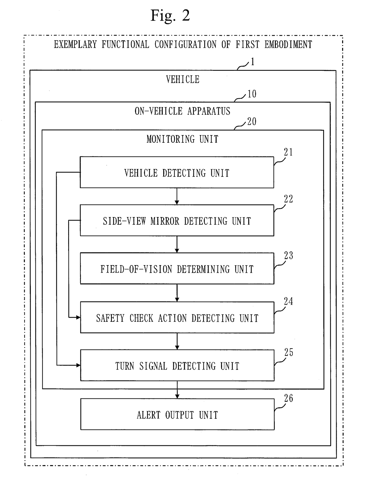
[0023]FIG. 1 illustrates an exemplary hardware configuration of an on-vehicle apparatus 10 according to the present embodiment. FIG. 2 illustrates an exemplary functional configuration of the on-vehicle apparatus 10 according to the present embodiment. Operation performed by the on-vehicle apparatus 10 corresponds to an alert output method and an alert output program.
[0024]As illustrated in FIGS. 1 and 2, the on-vehicle apparatus 10 is mounted on a vehicle 1.
[0025]First, with reference to FIG. 1, an exemplary hardware configuration of the on-vehicle apparatus 10 will be described.
[0026]The on-vehicle apparatus 10 is a computer, and is composed of a processor 11, a memory 12, a camera 13, a speaker 14, and a display 15.
[0027]The processor 11 executes programs.
[0028]The memory 12 stores therein programs that implement the functions of a monitoring unit 20 and an alert output unit 26 which are illustrated in FIG. 2.
[0029]Then, the processor 11 executes...
second embodiment
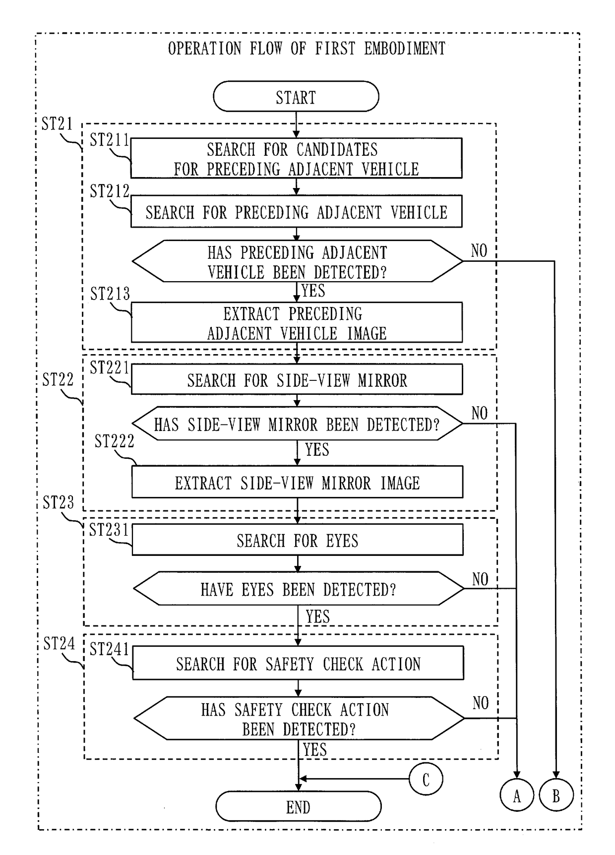
[0069]In the first embodiment, when safety check action has been detected, a turn signal lighting-up detection process is not performed; however, in a second embodiment, even when safety check action has been detected, a turn signal lighting-up detection process is performed.
[0070]In general, when a lane change is made, a driver checks side and rear safety. Hence, when safety check action by a driver of a preceding adjacent vehicle has been detected, it is considered that the driver of the preceding adjacent vehicle has an intention for a lane change. In a case in which the lighting up of a turn signal of the preceding adjacent vehicle has not been able to be detected when safety check action by the driver of the preceding adjacent vehicle has been detected, it is considered that the driver of the preceding adjacent vehicle has forgotten to light up the turn signal despite his / her intention for a lane change.
[0071]Hence, when the lighting up of a turn signal has not been detected de...
third embodiment
[0083]In the first and second embodiments, when the on-vehicle apparatus 10 cannot detect the eyes of a driver of a preceding adjacent vehicle, the on-vehicle apparatus 10 determines that the driver of the preceding adjacent vehicle cannot visually recognize the vehicle 1. Even if the eyes of the driver of the preceding adjacent vehicle cannot be detected in a photographed image of the camera 13, if the eyes of the driver of the preceding adjacent vehicle can be detected from a different position of the vehicle 1, then it is considered that the driver of the preceding adjacent vehicle can visually recognize the vehicle 1.
[0084]Hence, in the present embodiment, a plurality of cameras 13 that detect a preceding adjacent vehicle are disposed on a plurality of different positions of the vehicle 1, and the eyes of a driver of the preceding adjacent vehicle are detected by image analysis performed on a plurality of photographed images of the plurality of cameras 13.
[0085]Description of Co...
PUM
 Abstract
Description
Claims
Application Information
 - R&D
- Intellectual Property
- Life Sciences
- Materials
- Tech Scout
- Unparalleled Data Quality
- Higher Quality Content
- 60% Fewer Hallucinations
Browse by: Latest US Patents, China's latest patents, Technical Efficacy Thesaurus, Application Domain, Technology Topic, Popular Technical Reports.
© 2025 PatSnap. All rights reserved.Legal|Privacy policy|Modern Slavery Act Transparency Statement|Sitemap|About US| Contact US: help@patsnap.com


