
Equipment, system and method for delivery of high pressure fluid

Active Publication Date: 2018-11-15
MGB OILFIELD SOLUTIONS LLC
View PDF10 Cites 130 Cited by
  • Summary
  • Abstract
  • Description
  • Claims
  • Application Information

AI Technical Summary

Benefits of technology

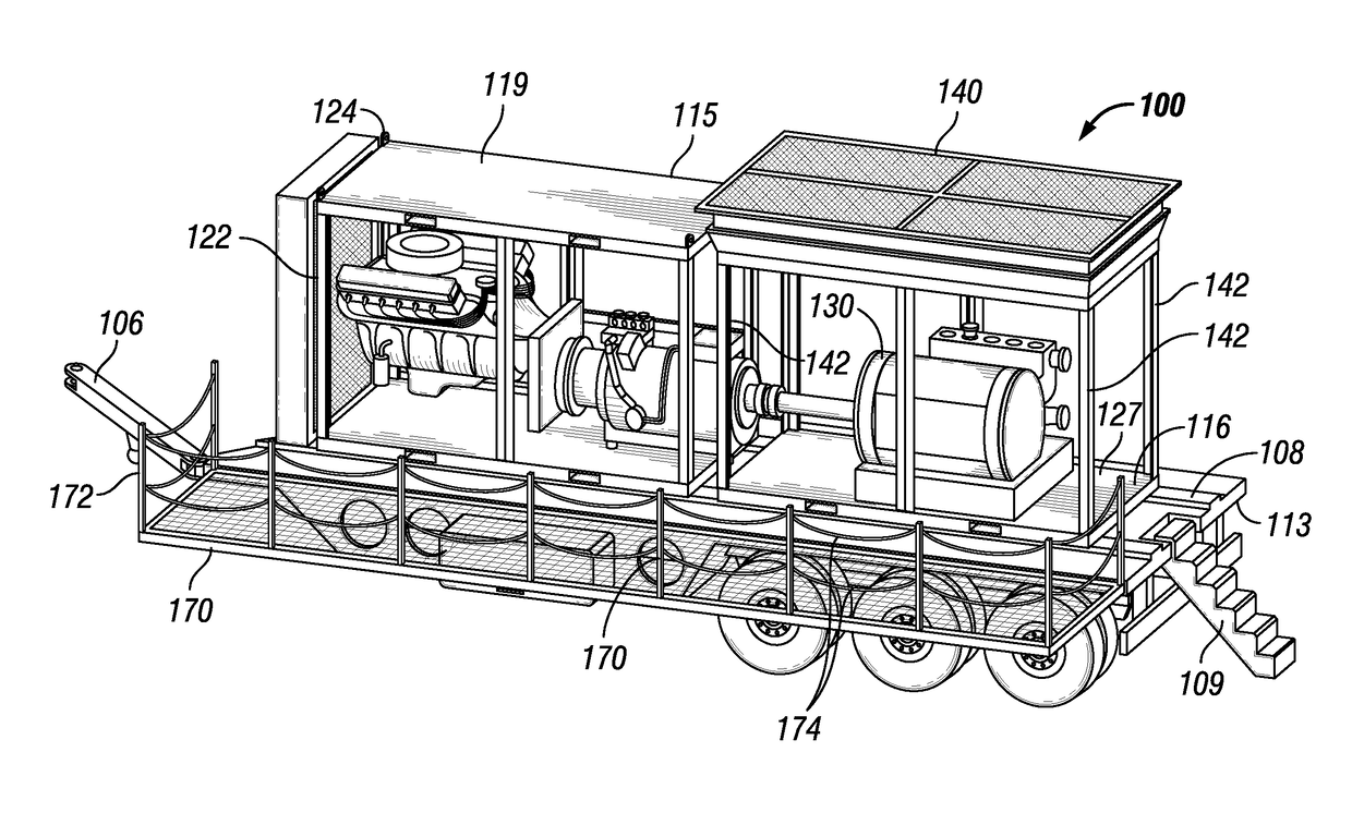
This patent describes a mobile hydraulic fluid delivery system that includes a chassis, power, pump, and cooling sub-assemblies that can be easily attached and removed from the chassis. Additionally, the system has a platform that can be towed and has a unique configuration with the sub-assemblies. The technical effects of this invention include improved portability, flexibility, and efficiency of a hydraulic fluid delivery system.

Problems solved by technology

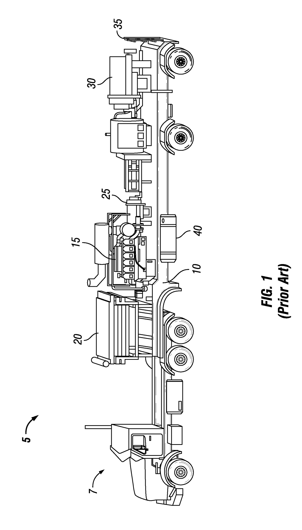
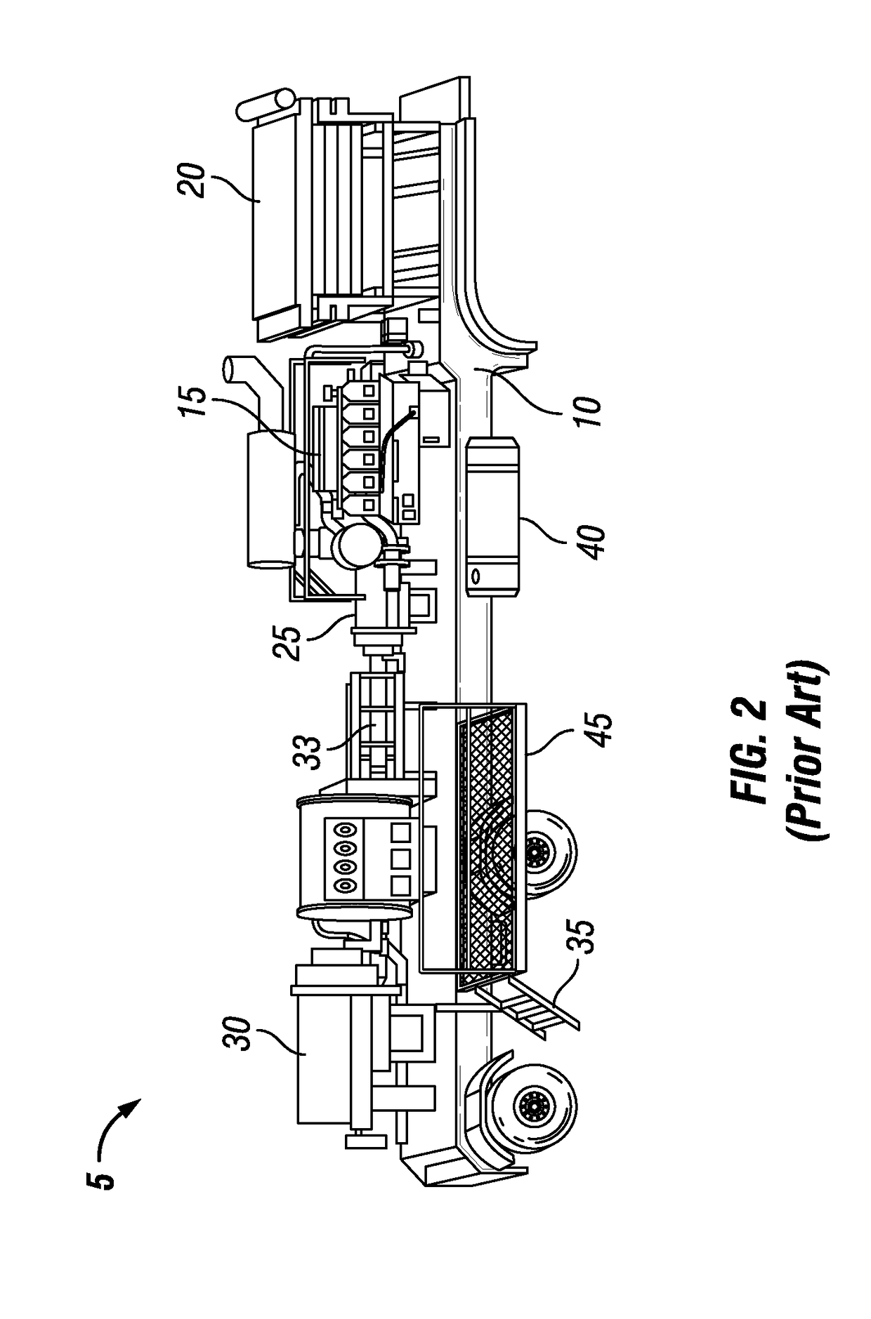
Trailer and skid mounted hydraulic fracturing fluid pumping units are typically quite long and are often difficult to maneuver at a well site.
Moreover, trailer or skid mounted hydraulic fracturing fluid pumping units currently in use are complex in design rendering such units difficult and / or expensive to operate, monitor, and repair.

Method used


Image

  • Equipment, system and method for delivery of high pressure fluid
  • Equipment, system and method for delivery of high pressure fluid
  • Equipment, system and method for delivery of high pressure fluid

Examples


example 1

[0126]With attention to FIG. 10, one non-limiting embodiment of the system 100 may include the following design characteristics:[0127]Chassis 105: —Two main parallel support beams constructed from high tensile steel, mild steel, or aluminum.[0128]Support surface 112 material constructed from high tensile steel, mild steel, or aluminum.[0129]Opposing body members 152, 153 constructed from mild steel, aluminum, or glass reinforced plastic.[0130]Two fuel tanks, each constructed from stainless steel and having a volume from about 200.0 liters (52.83 gallons) to about 2500.0 liters (660.4 gallons).[0131]Axle system using air ride suspension from Meritor, Inc., Troy, Mich.[0132]Total of 8, 12 or 16 tires[0133]Dimensions: Height: 1.5 meters (4.92 feet)[0134]Width: 2.62 meters (8.6 feet)[0135]Length: 10.66 meters (35.0 feet)[0136]Engine 120: —Caterpillar 3512C HD SCAC; Cummins QSK50 (optional); MTU 12V4000 (optional)[0137]2500 BHP @1950 RPM[0138]Emissions Certified[0139]Heavy duty air clean...

example 2

[0152]With reference to FIGS. 21 and 22, a chassis 205 may be provided having the following dimensions:

[0153]D1: 121.92 cm (48.0 inches)

[0154]D2: 375.92 cm (148.0 inches)

[0155]D3: 45.72 cm (18.0 inches)

[0156]D4: 1148.28 cm (452.08 inches)

[0157]D5: 259.08 cm (102.0 inches)

[0158]D6: 1069.31 cm (420.99 inches)

[0159]D7: 60.96 cm (24.0 inches)


PUM


Abstract

The application is directed to a system and method for hydraulic fluid delivery including the delivery of high pressure fluid in hydraulic fracturing operations. The system of this application is operationally configured to reduce the footprint at a well site and, in one aspect, includes a towable platform carrying a power sub-assembly, a pump sub-assembly and a cooler sub-assembly each of which is releasably attachable to the platform. Each sub-assembly may be removed from the platform without disturbing the relationship between the platform and the remaining sub-assemblies attached thereto.

Description

CROSS-REFERENCE TO RELATED APPLICATIONS[0001]This application claims benefit of U.S. Provisional Patent Application Ser. No. 62 / 505,066, filed on May 11, 2017, the content of which is hereby incorporated by reference in its entirety. This application also claims benefit of U.S. Provisional Patent Application Ser. No. 62 / 617,164, filed on Jan. 12, 2018, the content of which is hereby incorporated by reference in its entirety.STATEMENT REGARDING FEDERALLY SPONSORED RESEARCH OR DEVELOPMENT[0002]Not applicable.BACKGROUND OF THE INVENTION[0003]The field of the application relates generally to pumping operations and high pressure fluid pumping operations used to stimulate production from an oil or gas well.[0004]Hydraulic fracturing, sometimes called “fracing” or “fracking” is a process for increasing the flow of oil or gas from a well. Fracking typically involves pumping specific types of fluids into a well bore under pressures that are high enough to fracture an earthen formation. For c...

Claims


Application Information

Patent Timeline
IPC IPC(8): E21B43/26B60P3/00F04B17/05F04B17/06
CPCE21B43/26B60P3/00F04B17/05F04B17/06F04B47/02F04B53/22E21B43/2607
Inventor BISHOP, MARK DANIEL
Owner MGB OILFIELD SOLUTIONS LLC
Learn More