Rear lamp assembly

a technology for rear lamps and assemblies, applied in fixed installation, transportation and packaging, light and heating equipment, etc., can solve the problems of high cost of leds, increased cost, and increased cos

Active Publication Date: 2012-07-05
NORTH AMERICAN LIGHTING +1
View PDF3 Cites 12 Cited by
  • Summary
  • Abstract
  • Description
  • Claims
  • Application Information

AI Technical Summary

Benefits of technology

[0012]FIG. 6 illustrates a simplified sectional view of section A-A from FIG. 3 shown from the top view and illustrating a ray trace;
[0013]FIG. 7A illustrates a simplified sectional view of section B-B from FIG. 3 shown from the side view and illustrating a ray trace;
[0014]FIG. 7B illustrates a simplified sectional view of section of an alternative embodiment of the present invention shown from the side view and illustrating a ray trace;

Problems solved by technology

While the use of LEDs provides certain benefits in some lighting applications, the use of LEDs may be more expensive as multiple light sources must typically be used in order to meet the photometric requirements of a vehicle lamp.
Although the implementation of LEDs in rear automotive lamp assemblies is highly desirable, the high cost of LEDs prevents engineers and designers from implementing the LEDs into rear automotive lamp assemblies.
The addition of lens optics or having an inner lens component to the lamp may increase cost, and styling requirements of vehicle manufactures sometimes dictate that the lamp has a smooth clear lens so that the customers can easily see into the lamp.

Method used


Image

  • Rear lamp assembly
  • Rear lamp assembly
  • Rear lamp assembly

Examples


Embodiment Construction

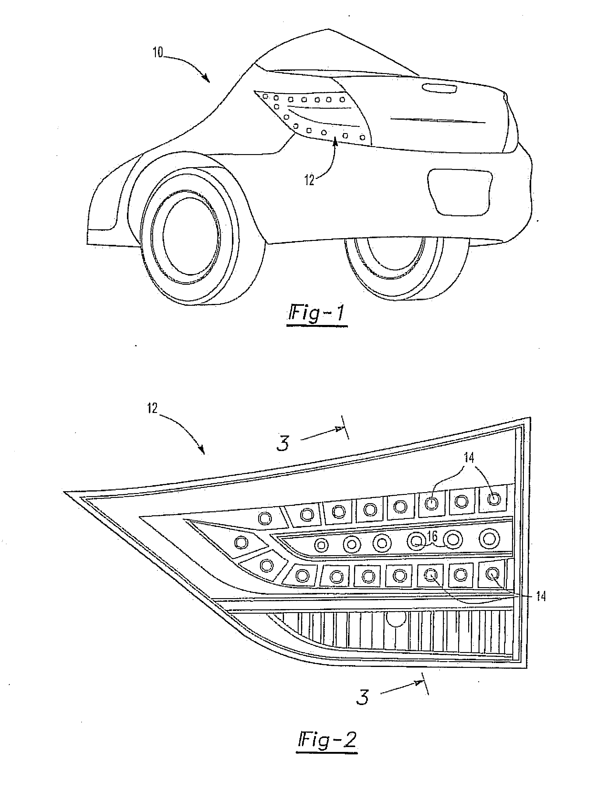
[0021]The automotive lamp assembly 12 replicates the appearance of a plurality of LEDs. The automotive lamp assembly 12 does not include the use of LEDs. The automotive lamp assembly 12 provides for a plurality of LED light reflection points 14. The automotive lamp assembly further includes decorative element 16.

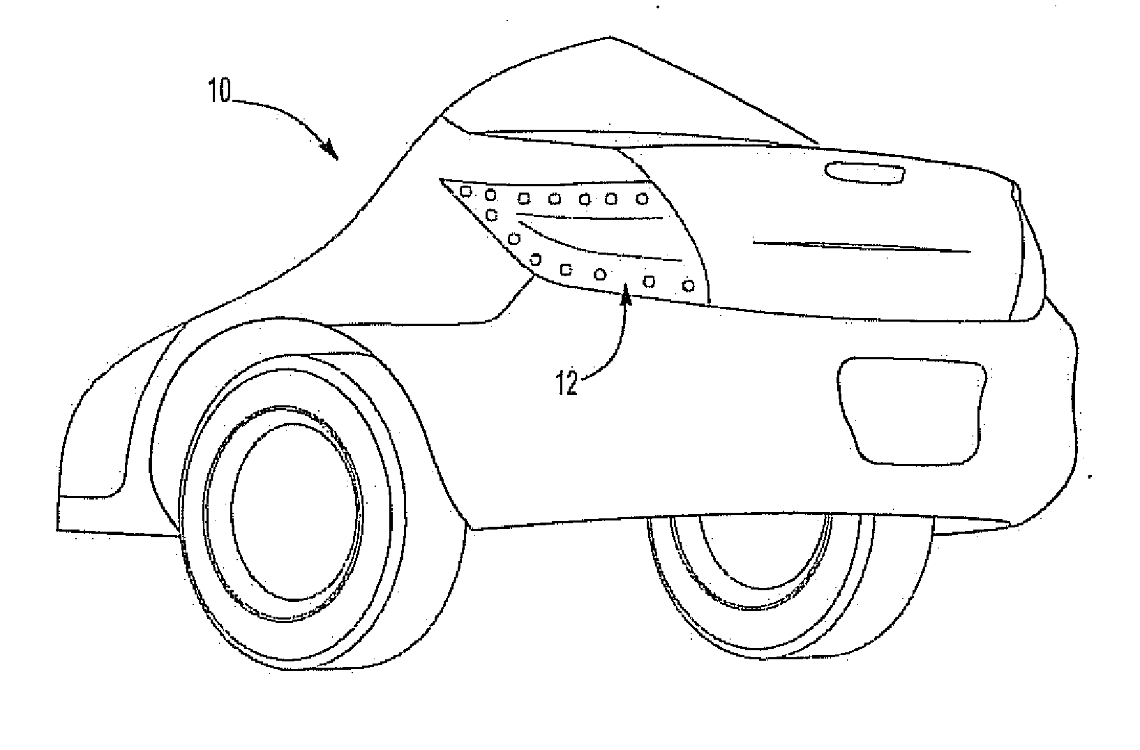
[0022]The exemplary lamp assembly 12 may be a tail lamp which may be provided on the rear of a vehicle. The lamp assembly 12 may be provided on the vehicle body, or the lamp may be disposed on another surface of the vehicle, such as the trunk or deck lid of the vehicle. Moreover, the lamp may be any type of lamp including, but not limited to, a signal or reverse lamp, not just the exemplary tail lamp as illustrated.

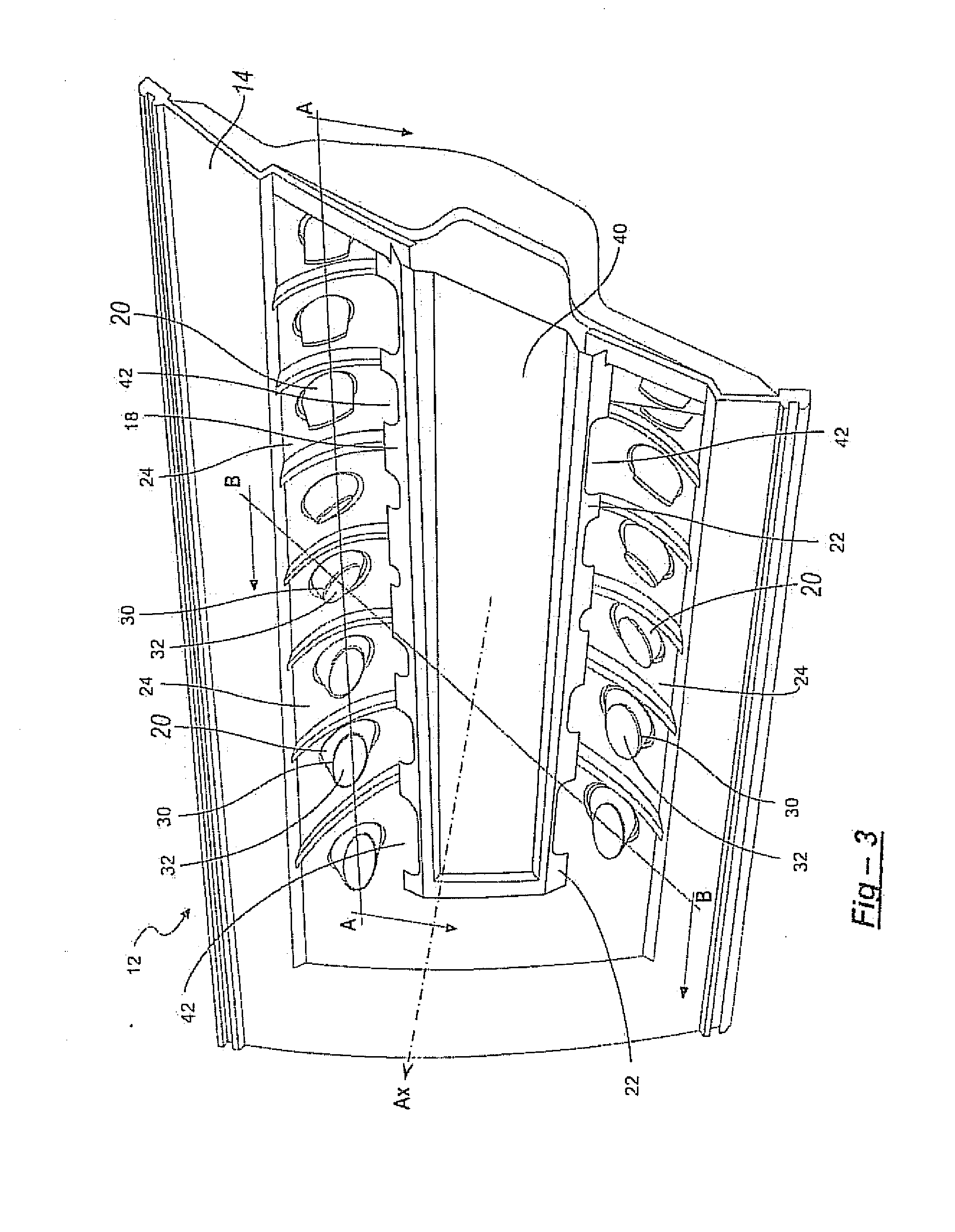
[0023]The lamp assembly 12 includes a housing 26 which may be enclosed by an outer lens 60. The lamp assembly 12 may include a plurality of reflectors 30 and spaced apart by respective connecting surfaces 24 which may be disposed or formed on the housing 26. In ot...


PUM


Abstract

A rear automotive lamp assembly is provided replicating the appearance of a plurality of distinct illumination sources, such as light emitting diodes. The lamp assembly having a light source, at least one reflector, the reflectors having reflective surfaces, the reflective surfaces operable to reflect light from the light source. The reflectors spaced apart and oriented such that light rays from the light source are incident to each of the reflective surfaces are reflected towards a viewing direction. A shield further disposed between the light source and the reflective surface of the reflector. The shield including a plurality of open sections or cutouts thereby allowing a generally collimated light beam from the light source to shine on the reflective surface such that each of the reflective surfaces of the at least one reflector appears as a distinct illumination source from the viewing direction. The openings vary in size and dimension along the length of the shield.

Description

FIELD OF THE INVENTION[0001]This invention relates generally to automotive lamp assemblies. In particular, this invention relates to a rear automotive lamp assembly replicating the appearance of a plurality of distinct illumination sources.BACKGROUND OF THE INVENTION[0002]For decades, conventional exterior vehicle lighting has relied on light sources such as incandescent or halogen lamps, for example. Relatively recent advances in technology have allowed vehicle lamps to incorporate other light sources into vehicle lighting applications. Some vehicle lamps have recently been designed to incorporate light emitting elements, such as light emitting diodes (LEDs), for use in exterior vehicle lamps. While the use of LEDs provides certain benefits in some lighting applications, the use of LEDs may be more expensive as multiple light sources must typically be used in order to meet the photometric requirements of a vehicle lamp.[0003]Although the implementation of LEDs in rear automotive la...

Claims


Application Information

Patent Timeline
Patent Type & Authority Applications(United States)
IPC IPC(8): F21S8/10
CPCF21S48/2218F21S48/214F21S48/234F21S48/25F21S43/13F21S43/255F21S43/31F21S43/50
Inventor OSTROWSKI, MICHALSTADTHERR, DIANNASHARMA, MANISHZHU, YIJUNG
Owner NORTH AMERICAN LIGHTING
Why Eureka
Try Eureka