

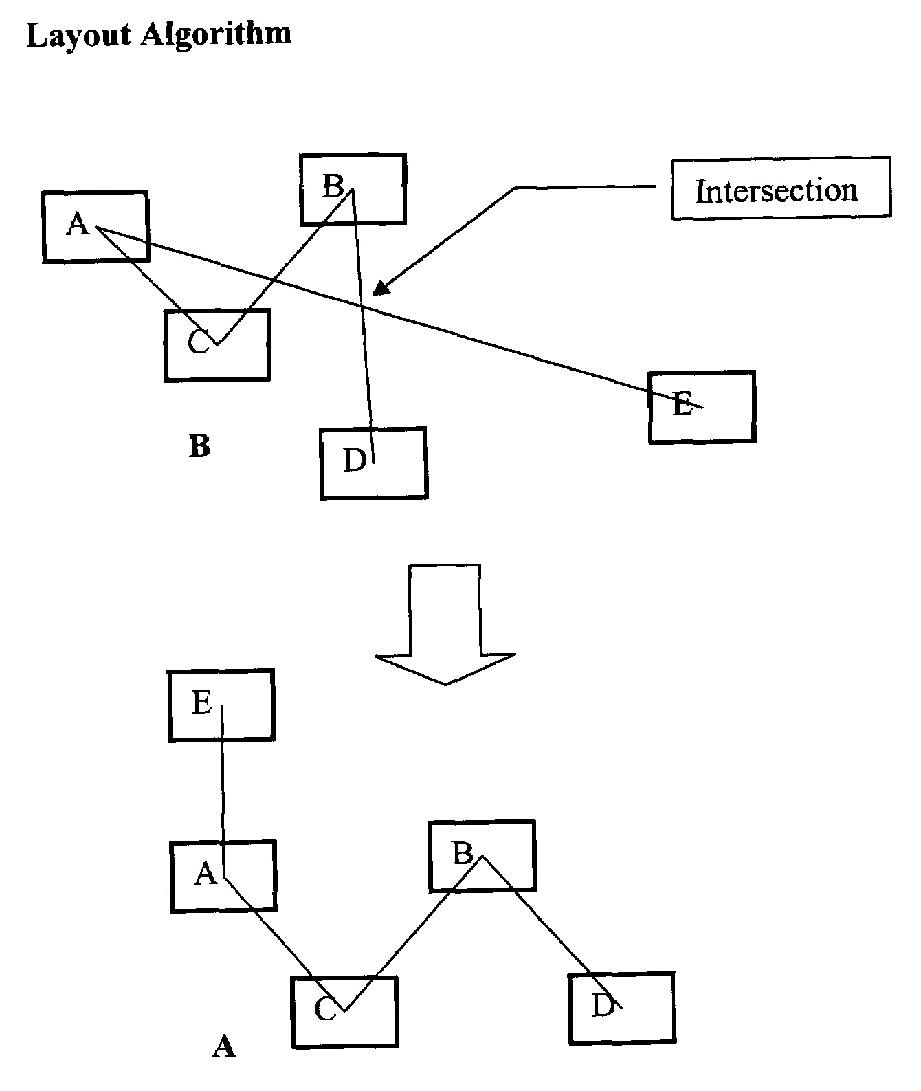
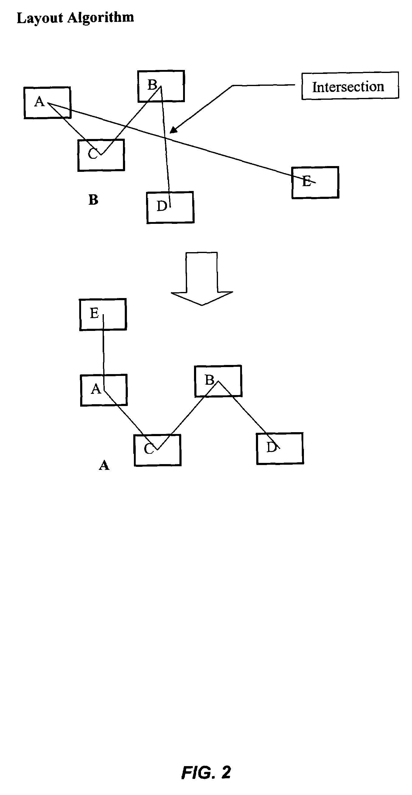
Algorithm for automatic layout of objects in a database
a database and object technology, applied in the field of automatic layout of objects in databases, can solve the problems of difficult to determine to which object nodes the connector line is associated, difficult for users to make much sense of the display, and difficult for users to determine the connection of the node to the object node, so as to improve the visual understanding of the network and simplify the network view
- Summary
- Abstract
- Description
- Claims
- Application Information
AI Technical Summary
Benefits of technology
Problems solved by technology
Method used
Image

Examples
Embodiment Construction
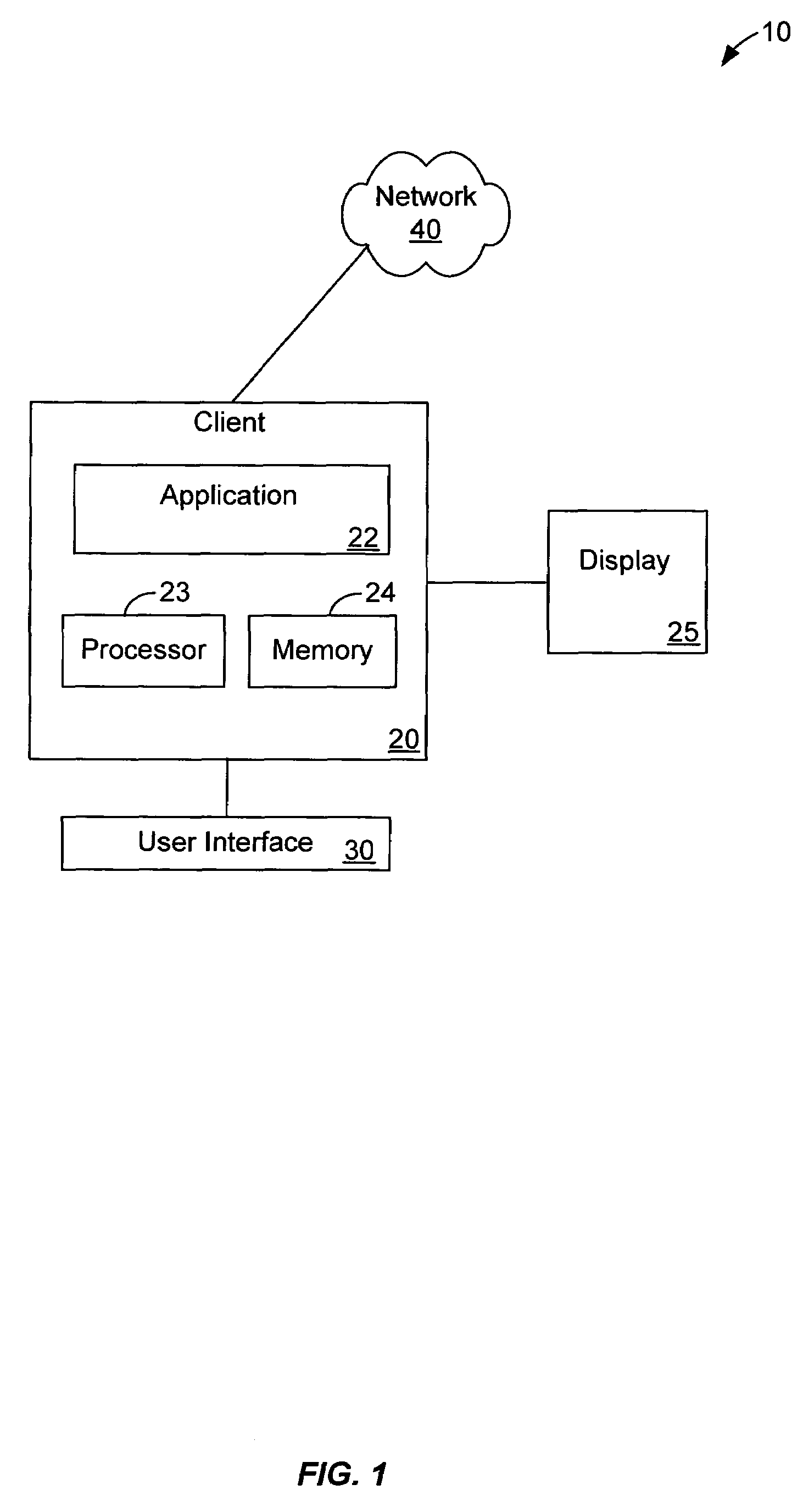
[0017]FIG. 1 illustrates an exemplary display system 10 according to the present invention. Display system 10 includes a client device 20, coupled to, or including a display device 25 and a user interface device 30. Client device 20 could be a desktop personal computer, workstation, laptop computer, or any other computing device. Client device 20 preferably includes components capable of interfacing directly or indirectly with a network 40. Network 40 can be the Internet, a local area network (LAN), wide area network (WAN), virtual private network (VPN) or any other type of network. Each client 20 typically runs an application program 22 allowing a user of client 20 to create and visualize a topology of network nodes as will be discussed in more detail below. Each client device 20 also typically includes one or more user interface devices 30, such as a keyboard, a mouse, touchscreen, pen or the like, for interacting with a graphical user interface (GUI) provided by the application p...
PUM
 Abstract
Description
Claims
Application Information