Discarded packet indicator

a technology of discarded packets and indicators, applied in the direction of error prevention/detection by transmission repeat, error detection/prevention using signal quality detectors, digital transmission, etc., can solve the problem of increasing the quality of video, and achieve the effect of high-quality video experien

Active Publication Date: 2007-06-21
ALCATEL LUCENT SAS
View PDF15 Cites 13 Cited by
  • Summary
  • Abstract
  • Description
  • Claims
  • Application Information

AI Technical Summary

Benefits of technology

[0026]FIG. 2 shows a more detailed view of a specific type of IP video network that may take advantage of the present invention, although the invention is not limited to this type of network. In FIG. 2, a VHE (video head end) 20 streams video packets to one or more IP video receivers 22. The IP video receivers 22 translate the video packets to video for video monitors 24. To get to the IP video receivers 22, the data must pass through a public / private network 26 which may include a plurality of routers, including edge router 28. The output of edge router 28 is received by DSLAM (digital subscriber line access multiplexer) element 30, where the data is placed on twisted pair lines 31. A DSL modem 32 on the user premises communicates between the DSLAM element 30 and the IP video receivers 22 through premises router 34.
[0027] It should be noted that the specific embodiment shown in FIG. 2 is directed to IP video services over a DSL connection at the user premises. Other configurations for communication to the premises could also be used with the present invention, including digital cable, wireless communications, and optical fiber.
[0028] In operation, the video head end streams video information to the IP video receivers 22. For live video broadcasts, such as a live television signal, the video data is typically sent as a multicast transmission. For on-demand video, unicast transmission may be used.
[0029]FIG. 3 illustrates a greatly simplified view of a packet of the type that would be used to convey video or audio data. The packet 40 includes a header, which includes information on addressing, status, and priority indicators and a payload, which includes the audio and video data. In most video protocols, such as MPEG (Motion Picture Experts Group), MPEG2 and MPEG4, among others, the payload often carries differential information (i.e., the information describing how a frame varies from a previously transmitted frame) and, hence, the payload may vary in size dramatically from packet to packet in a stream. A more detailed illustration is shown in FIG. 6.
[0030]FIG. 4a illustrates a simplified view of an intermediary network element 14. The intermediary network element 14 includes a FIFO memory 50, an input from receiving packets, an output 54 for forwarding packets, and control circuitry 56 for controlling the FIFO 50. Packets A-E are shown in the FIFO memory 50, along with free space.
[0031] As described above, packets may be received faster than they can be sent, which will cause a FIFO overrun. One reason for an overrun may be the limited bandwidth of the DSL connection between the DSLAM element 30 and the DSL modem element 32. As more channels are being requested at the user premises, the number of packets multiplexed at the DSLAM element 30 for that user premises increases. In general, a commercial IP television system will be designed such that the bandwidth will support a certain number of data streams for the premises; however, if multiple channels are sending large information packets simultaneously, congestion may occur which will require discarding some packets in the data stream.

Problems solved by technology

In a video application, the increase in the quality of the video will be apparent when early error concealment is used instead of displaying an obvious glitch (objectionable video artifact) caused by a missing packet.

Method used


Image

  • Discarded packet indicator
  • Discarded packet indicator
  • Discarded packet indicator

Examples


Embodiment Construction

[0022] The present invention is best understood in relation to FIGS. 1-7 of the drawings, like numerals being used for like elements of the various drawings.

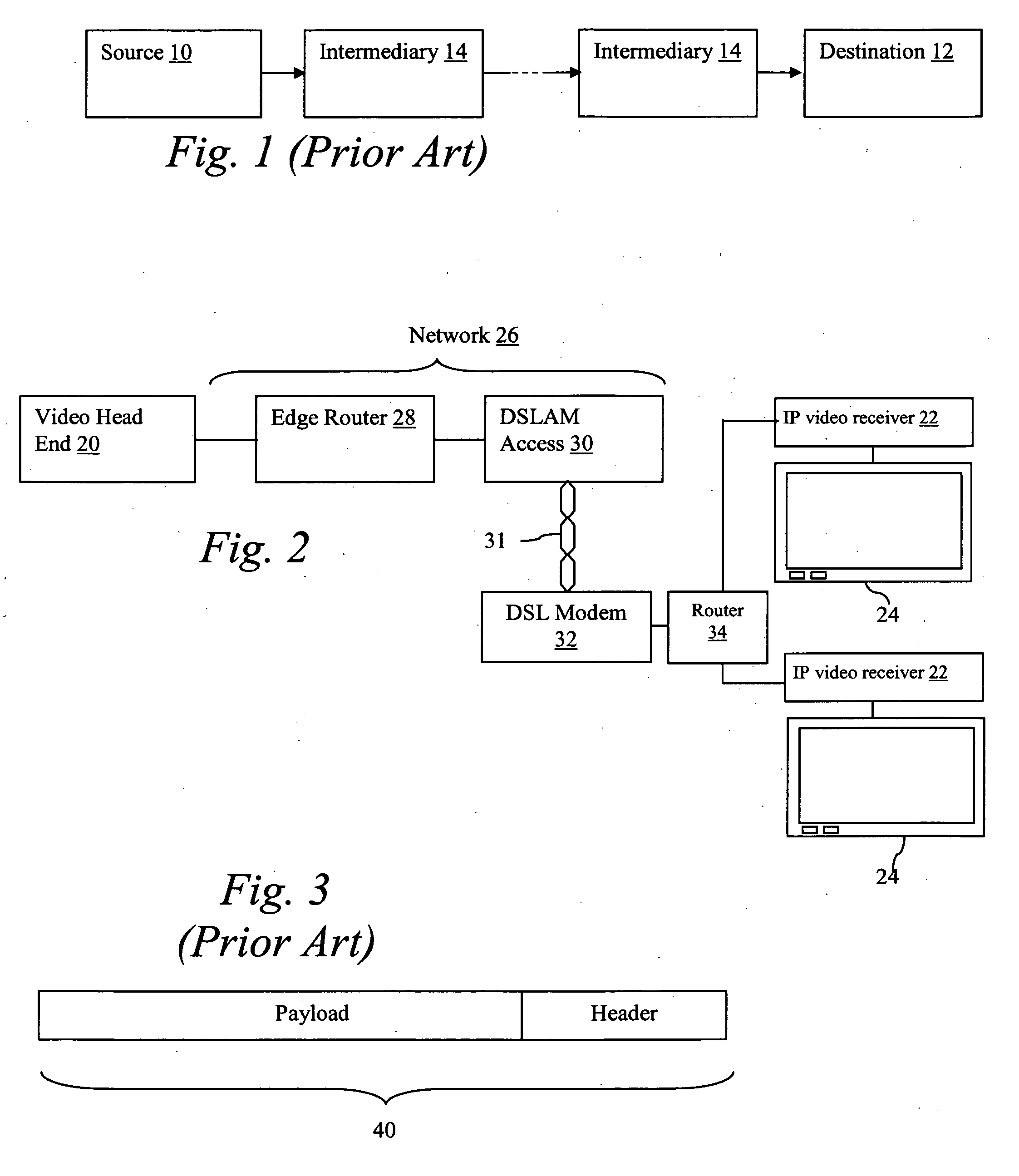
[0023]FIG. 1 illustrates an example of a path between a source device 10 and a destination device 12 in a data network. The source device 10 could be, for example, a video server or an audio server, and the destination device could be a user computing device (such as a desktop / mobile computer, handheld computer / PDA, or smart phone with network access), an internal or external (“set-top”) IP video receiver, or an internal or external IP audio receiver. Between source device 10 and destination device 12, there are one or more intermediate network elements 14 which pass information between the source device 10 and destination device 12. The intermediate network elements 14 could be, for example, Internet and / or proprietary network routers and multiplexers.

[0024] In operation, the source device 10 streams data to the destination 1...


PUM


Abstract

A source device (10) sends information to a destination device (12) through intermediary network elements (14). If an intermediary network element (14) needs to discard one or more packets of information, it sends a smaller informational packet to the destination device (12). Upon receiving the informational packet, the destination device can immediately begin correctional procedures.

Description

STATEMENT OF FEDERALLY SPONSORED RESEARCH OR DEVELOPMENT [0001] The U.S. Government has a paid-up license in this invention and the right in limited circumstances to require the patent owner to license others on reasonable terms as provided for by the terms of Award No. 70NANB3H3053 awarded by National Institute of Standards and Technology.BACKGROUND OF THE INVENTION [0002] 1. Technical Field [0003] This invention relates in general to digital information delivery networks and, more particularly, to a method and apparatus for indicating discarded packets in a network. [0004] 2. Description of the Related Art [0005] In a digital information delivery network, between a source device and a destination device, packets of data may be lost for a variety of reasons. Some packets are randomly lost due to uncontrollable errors—for example, errors caused by noise on a transmission line, synchronization issues, etc. Some packets are lost due to constraints in network resources (e.g. transmissi...

Claims


Application Information

Patent Timeline
Patent Type & Authority Applications(United States)
IPC IPC(8): H04L5/22H04L47/30H04L47/31H04L47/32
CPCH04L1/005H04L1/0066H04L1/08H04L1/20H04L29/06027H04L65/80H04L47/30H04L47/31H04L47/326H04L47/33H04L65/4076H04L47/10H04L65/611H04L65/1101
Inventor ZRINY, DONALD P.SKOOG, FREDERICK
Owner ALCATEL LUCENT SAS
Why Eureka
Try Eureka