Lamella for a Frictional Shift Element

a shift element and latching technology, applied in the direction of friction lining, mechanical actuated clutches, mechanical apparatus, etc., to achieve the effect of reducing the flow resistance of the second groove, high energy input into the starting component, and improving the flow originating from the third groove into the second groov

Inactive Publication Date: 2018-11-15
ZF FRIEDRICHSHAFEN AG
View PDF11 Cites 4 Cited by
  • Summary
  • Abstract
  • Description
  • Claims
  • Application Information

AI Technical Summary

Benefits of technology

[0012]Preferably, the opening points of the third grooves are arranged between the deflection points of the circumferential first groove. Alternatively thereto, the opening points can coincide with the radially outer deflection points of the first groove. According to yet another advantageous variant, the opening points of the third grooves can coincide with the radially inner deflection points of the first groove, i.e., can be congruent. As a result, the flow originating from the third grooves into the second grooves can be improved.
[0013]Preferably, the width of the circumferential first groove, the second grooves, and the third grooves is identical. According to one alternative embodiment, the width of the second grooves is greater than the width of the circumferential first groove. As a result, the flow resistance of the second grooves is reduced as compared to the flow resistance of the circumferential first groove, and therefore a penetration by the oil radially from the outside toward the inner edge of the disk is facilitated.
[0014]The disk according to the invention can be an integral part of a friction-locking shift element, for example of a multi-disk clutch or a multi-disk brake. In this case, multiple outer clutch disks and multiple inner clutch disks are successively arranged so as to alternate in the axial direction. The outer clutch disks are connected to an outer disk carrier in a rotationally fixed and axially displaceable manner. The inner clutch disks are connected to an inner disk carrier in a rotationally fixed and axially displaceable manner. The disks according to the invention form either the inner clutch disks or the outer clutch disks. The friction-locking shift element includes a device in this case, which is designed for feeding fluid radially from the outside toward the outer edge of the disk according to the invention. The friction-locking shift element designed in such a way can be an integral part of a transmission for a motor vehicle. In this case, the friction-locking shift element operates as a starting component in the drive train of a motor vehicle. Such a starting component allows for a slip state between the drive source and the driving wheels of the motor vehicle during the starting process. In this case, particularly in the case of a starting process under high load, for example on an uphill grade and with a loaded motor vehicle trailer, a high input of energy into the starting component can occur. Due to the improved cooling effect, which is more uniform across the radius of the frictional surface, the friction-locking shift element is particularly suitable for the application as a starting component.

Problems solved by technology

This is undesirable.

Method used


Image

  • Lamella for a Frictional Shift Element
  • Lamella for a Frictional Shift Element
  • Lamella for a Frictional Shift Element

Examples


Embodiment Construction

[0024]Reference will now be made to embodiments of the invention, one or more examples of which are shown in the drawings. Each embodiment is provided by way of explanation of the invention, and not as a limitation of the invention. For example, features illustrated or described as part of one embodiment can be combined with another embodiment to yield still another embodiment. It is intended that the present invention include these and other modifications and variations to the embodiments described herein.

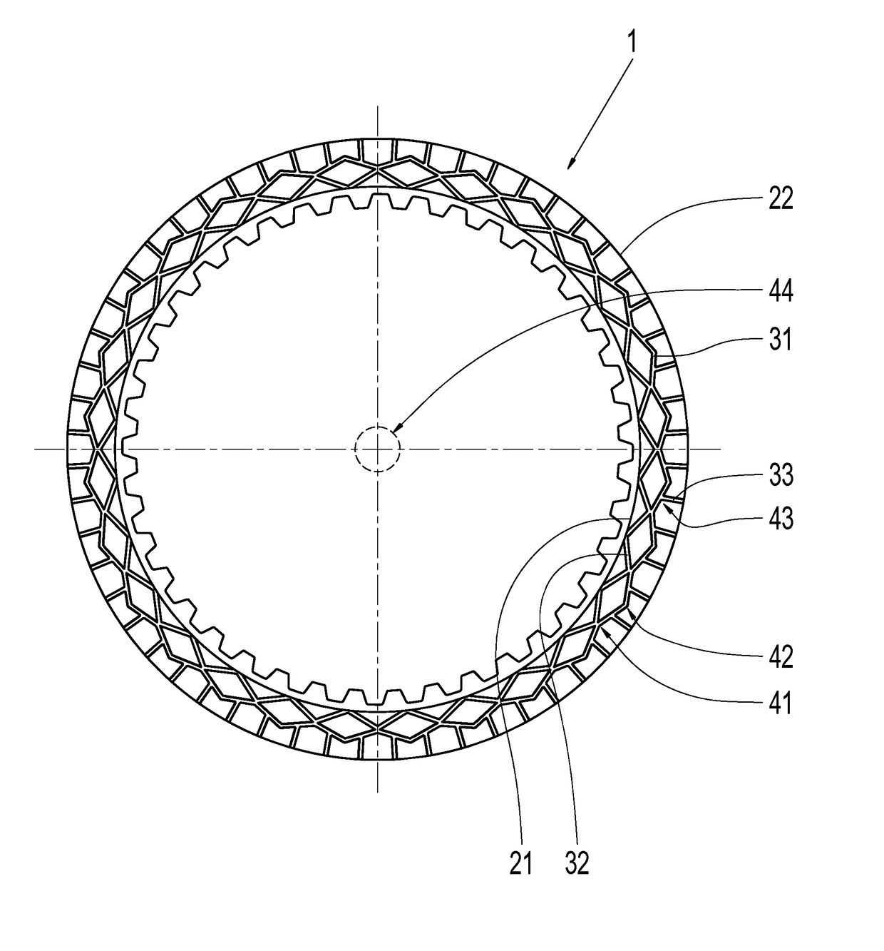
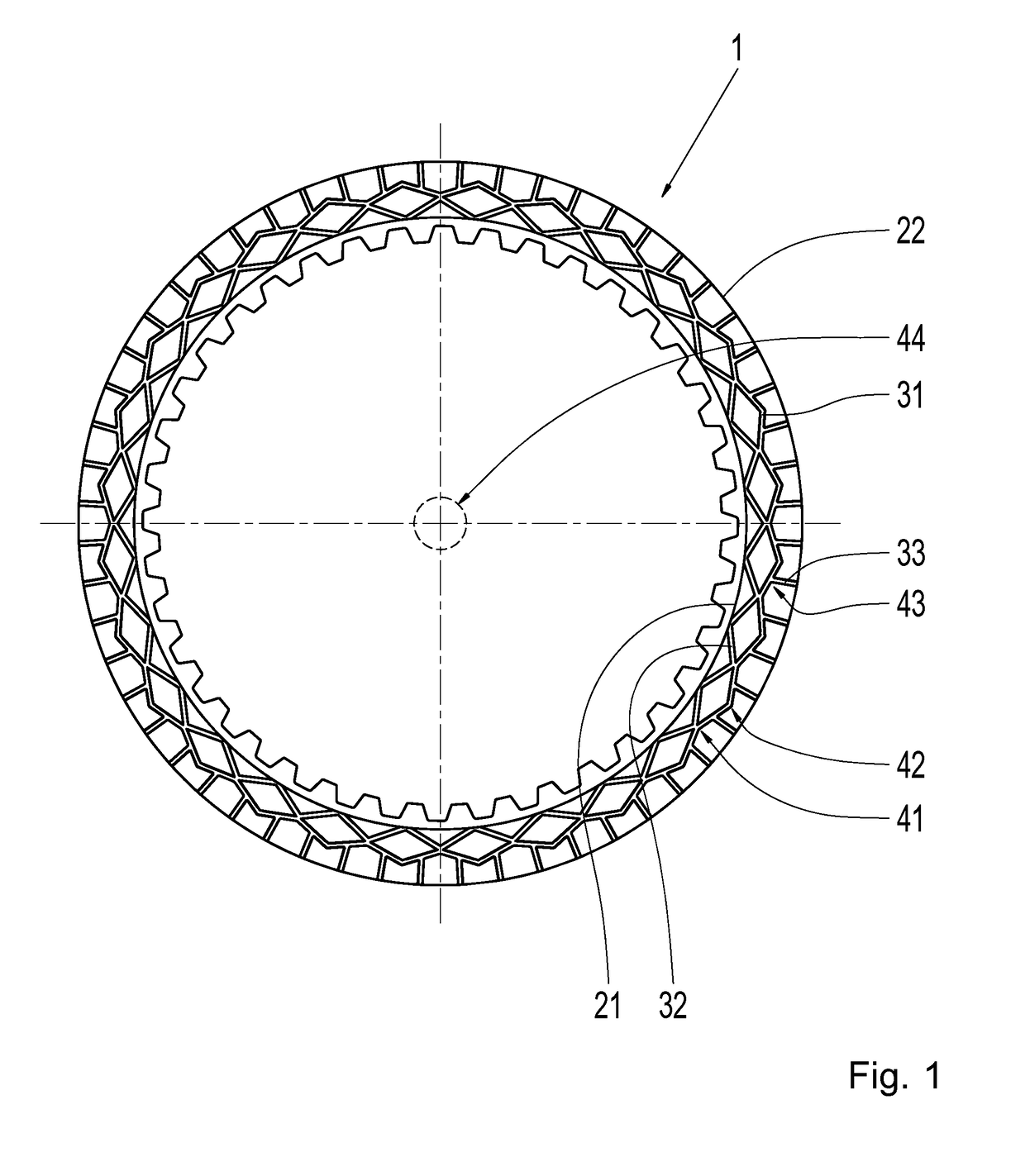
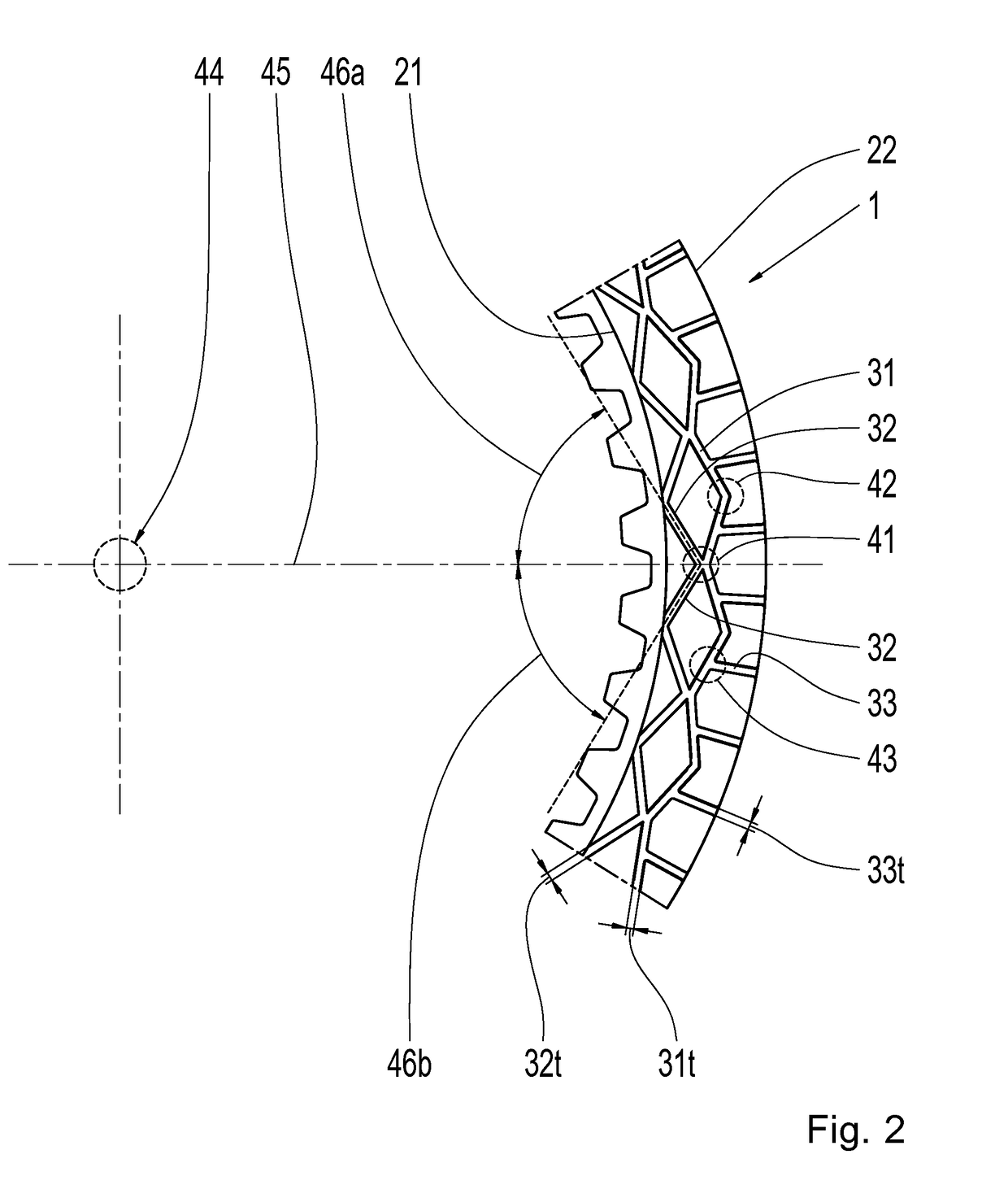
[0025]FIG. 1 shows a face-end view of a disk 1, arranged around a center of rotation 44 of the disk 1. The disk 1 includes an annular frictional surface which includes an inner edge 21 and an outer edge 22. Provided in the frictional surface is a symmetrical groove pattern consisting of a circumferential first groove 31, multiple second grooves 32, and multiple third grooves 33. The first groove 31 extends, in a zig-zag or undulating manner, between radially internal deflection po...


PUM


Abstract

A disk (1) for a friction-locking shift element includes an annular frictional surface with a circumferential first groove (31), a plurality of second grooves (32), and a plurality of third grooves (33). At least a section of each of the second grooves (32) at a respective radially internal deflection point (41) is oriented to form an angle (46a) with a line (45) between a center of rotation (44) of the disk (1) and the respective radially internal deflection point (41). The angle (46a) is no less than thirty-five degrees and no greater than seventy-five degrees.

Description

FIELD OF THE INVENTION[0001]The invention relates generally to a disk for a friction-locking shift element. The invention further relates generally to a friction-locking shift element including such a disk, and to a transmission for a motor vehicle including such a friction-locking shift element.BACKGROUND[0002]International application WO 2009 / 021569 A1 describes a frictional part for a device operating in a friction-locking manner, said part including an annular frictional surface which includes an inner edge and an outer edge, wherein provided in the frictional surface is a circumferential first groove, which extends between radially internal and radially external deflection points in a zig-zag or undulating manner, multiple second grooves, which originate from the inner edge and extend to the internal deflection points, and multiple third grooves which originate from the outer edge and extend essentially in the radial direction into the circumferential first groove and open, at ...

Claims


Application Information

Patent Timeline
Patent Type & Authority Applications(United States)
IPC IPC(8): F16D13/64F16D13/72
CPCF16D13/648F16D13/72F16D2065/1312F16D2069/004F16D65/128F16D65/127F16D25/0638F16D25/123F16D13/74
Inventor LANGENKAEMPER, DERKGERTEISER, STEFFENSCHMIDT, STEFAN
Owner ZF FRIEDRICHSHAFEN AG
Why Eureka
Try Eureka