
Wireless detonator

a detonator and wireless technology, applied in the direction of proximity fuzes, electric fuzes, weapons, etc., can solve the problems of difficult to take into account, insufficient approximation, and technical problems

Active Publication Date: 2018-11-15
DETNET SOUTH AFRICA (PTY) LTD
View PDF68 Cites 3 Cited by
  • Summary
  • Abstract
  • Description
  • Claims
  • Application Information

AI Technical Summary

Benefits of technology

The invention is a wireless detonator that uses an energy source to fire an ignition element, a communication module and an energy harvesting unit to power the communication module. The detonator can also have a sensor to prevent accidental firing and can detect specific molecules in explosives. The detonator has a fuse and a switch for safely detonating the explosive at a predetermined time.

Problems solved by technology

This approach is, however, not completely satisfactory because a reed switch can be actuated erroneously by a stray magnetic field such as that generated, for example, by a current-carrying conductor.
This can present technical problems.
This can be difficult for account must be taken of the arduous conditions which can prevail in a mining environment.
Apart from these aspects, a wireless detonator is sensitive to power consumption.
Communication with the detonator consumes energy which is drawn from the on-board battery source.
Communication is slow through rock (when the detonator is installed in a borehole) and a short message can take a long time to be transmitted, during which period energy can continuously be drawn from the battery.

Method used


Image

  • Wireless detonator
  • Wireless detonator

Examples


Embodiment Construction

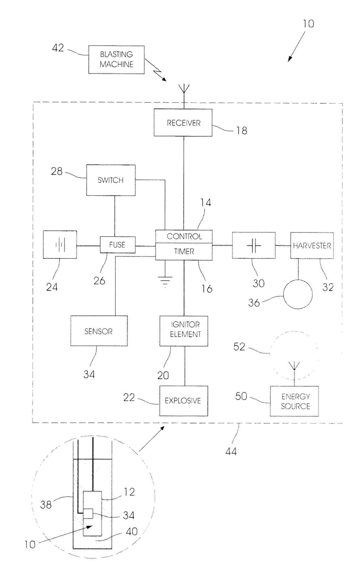
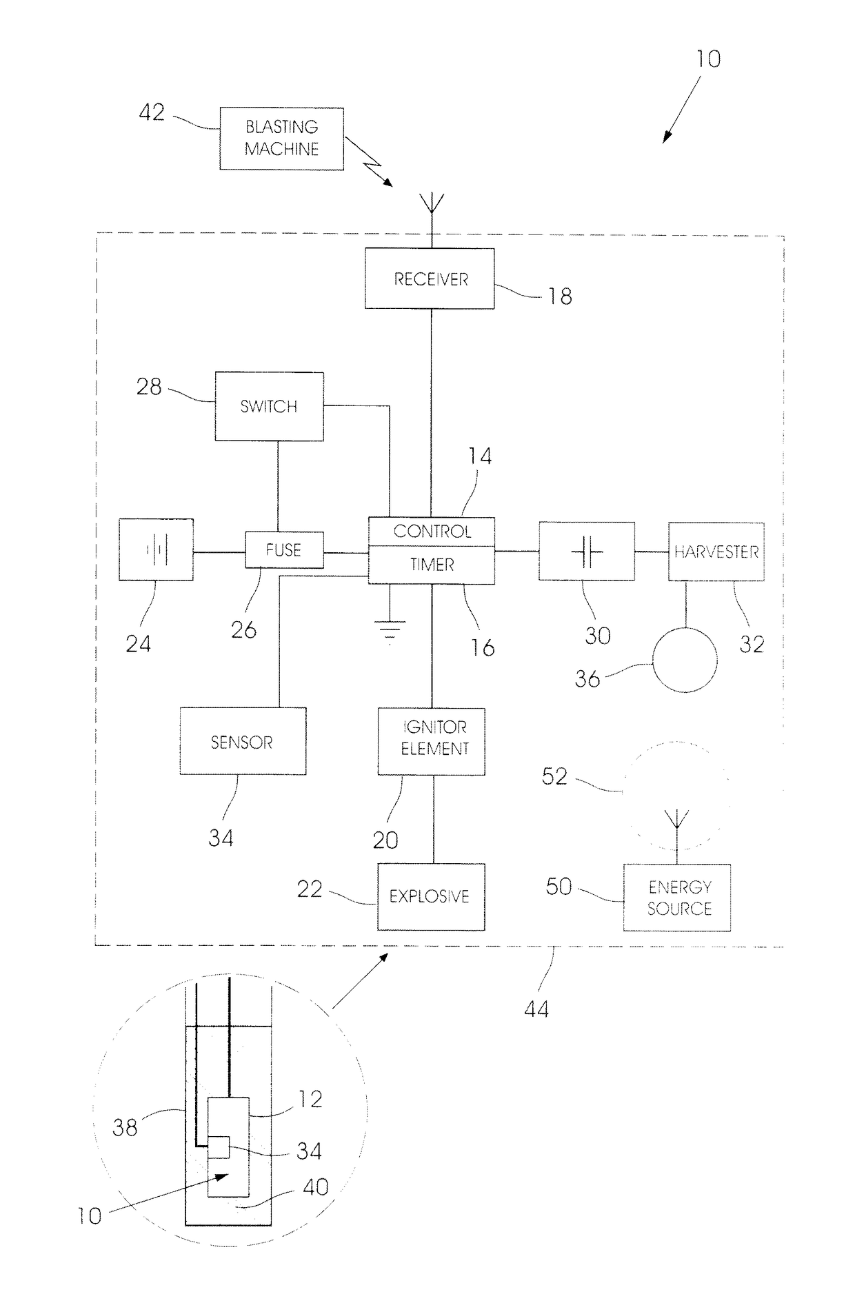
[0012]The accompanying drawing illustrates components of a detonator 10 according to the invention. The various components are mounted in a detonator can 12 (see insert drawing) according to requirement. The detonator 10 is one of a plurality of similar detonators (not shown) included in a blasting system at a blasting site.

[0013]The detonator 10 includes a control unit 14 which embodies a timer 16, a communication module 18, an ignition element 20, e.g. a bridge, a fuse or a hot-spot, a primary explosive 22, an on-board energy source in the form of a battery 24, a fuse 26 which is connected in a current path between the energy source 24 and the ignition element 20, a switch 28, an energy storage device 30 which, typically, is a battery or a capacitor, and an energy harvesting unit 32. Optionally the detonator 10 includes at least one sensor 34.

[0014]The control unit 14 is an application specific integrated circuit designed for the purpose. The communication module 18 normally inclu...


PUM


Abstract

A wireless detonator which includes a control unit, an ignition element, an energy source which is configured to fire the ignition element in response to a signal from the control unit, a communication module, and an energy harvesting unit which harvests energy from an external electromagnetic field which is used to power, at least, the communication module.

Description

BACKGROUND OF THE INVENTION[0001]This invention relates to a wireless detonator.[0002]In order for a wireless detonator to be used safely and effectively it must be activated (switched on), immediately before deployment. As a wireless detonator has an on-board energy source, typically a battery, a situation in which battery life can be exceeded before firing of the detonator takes place must be avoided.[0003]In one solution to this problem a detonator has been equipped with a magnetic reed switch which is enabled, using a suitable magnet, at the time the detonator is placed into a blast hole. This approach is, however, not completely satisfactory because a reed switch can be actuated erroneously by a stray magnetic field such as that generated, for example, by a current-carrying conductor.[0004]In a different approach an optical signal is used to enable the battery. This can present technical problems. Another technique requires the battery to be loaded into the detonator immediatel...

Claims


Application Information

Patent Timeline
IPC IPC(8): F42D1/05F42C13/04F42B3/12F42C11/06
CPCF42D1/05F42C13/04F42B3/121F42C11/06F42C11/00
Inventor VENTER, FRANCOISMULLER, ELMAR LENNOX
Owner DETNET SOUTH AFRICA (PTY) LTD
Learn More