
Magnetic Field Detection Sensor

Active Publication Date: 2018-11-15
YAZAKI CORP
View PDF2 Cites 4 Cited by
  • Summary
  • Abstract
  • Description
  • Claims
  • Application Information

AI Technical Summary

Benefits of technology

The present invention provides a magnetic field detection sensor that can broaden the range of magnetic field detection. The sensor uses a magnetoimpedance element that exhibits a M-shaped magnetoimpedance characteristic, which limits the range of magnetic field detection. The invention solves this problem by employing a first and second magnetism detection element that can detect magnetic fields in different directions and ranges. The sensor can generate a signal that reflects the magnetism detection states of both elements, allowing for a wider range of magnetic field detection. The invention also addresses the issue of limited detection accuracy in strong magnetic fields by employing an AC bias circuit that applies an AC bias current to the magnetic members. The invention provides a magnetic field detection sensor that can detect magnetic fields in a wide range from a weak magnetic field to a strong magnetic field.

Problems solved by technology

(1) The range of magnetic field detection is narrow.
(2) Since the magnetoimpedance characteristic of the magnetoimpedance element is M-shaped, in the case where an AC bias is used, a high-sensitivity measurement cannot be performed without applying an AC bias to such an extent that a steep-slope portion is reached. This increases the current consumption.
(3) Exhibiting an M-shaped magnetoimpedance characteristic, the magnetoimpedance element is larger in hysteresis than a magnetoimpedance element having a pyramid-shaped magnetoimpedance characteristic. This lowers the detection accuracy.
However, where a magnetic field is detected using the circuit having the configuration shown in FIG. 1 of Patent document JP-A-2015-92144, if an external magnetic field is too strong, necessary pulses do not appear at the output of a differentiation circuit shown in FIG. 6(d) of Patent document JP-A-2015-92144 to incur a state that a phase of such pulses cannot be detected and hence detection of a magnetic field is disabled.
Thus, the problem of the above item (1) cannot be solved.
Thus, in a strong magnetic field range, an impedance variation corresponding to a difference in the strength of a magnetic field is small, which leads to difficulty in detecting a strong magnetic field.
In particular, a strong magnetic field cannot be detected if detection of a weak magnetic field is enabled by increasing the detection sensitivity of the sensor.

Method used


Image

  • Magnetic Field Detection Sensor
  • Magnetic Field Detection Sensor
  • Magnetic Field Detection Sensor

Examples


Embodiment Construction

[0047]A specific embodiment of the present invention will be hereinafter described with reference to the drawings.

200>

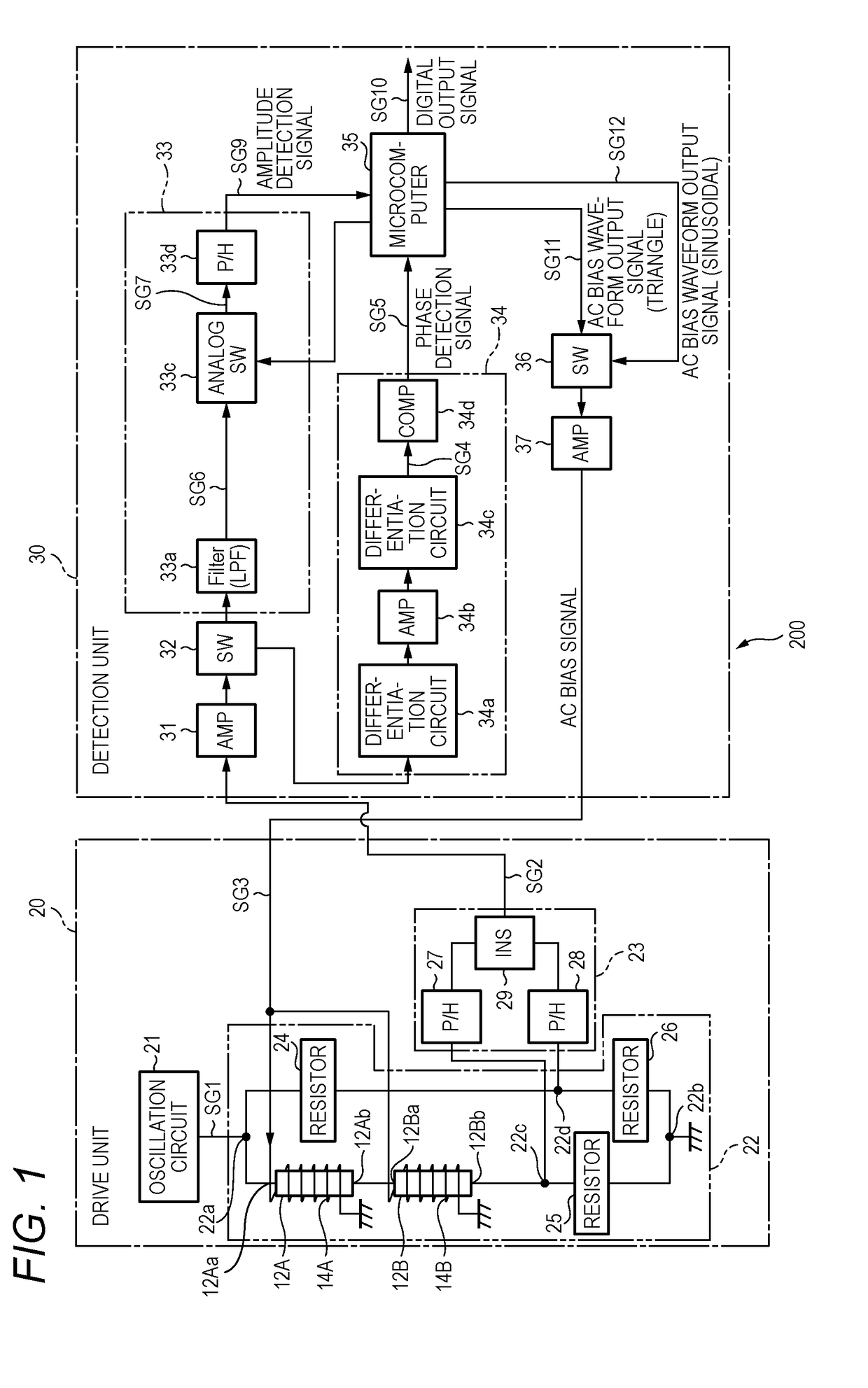
[0048]FIG. 1 shows an example configuration of a magnetic field detection sensor 200 according to the embodiment of the invention.

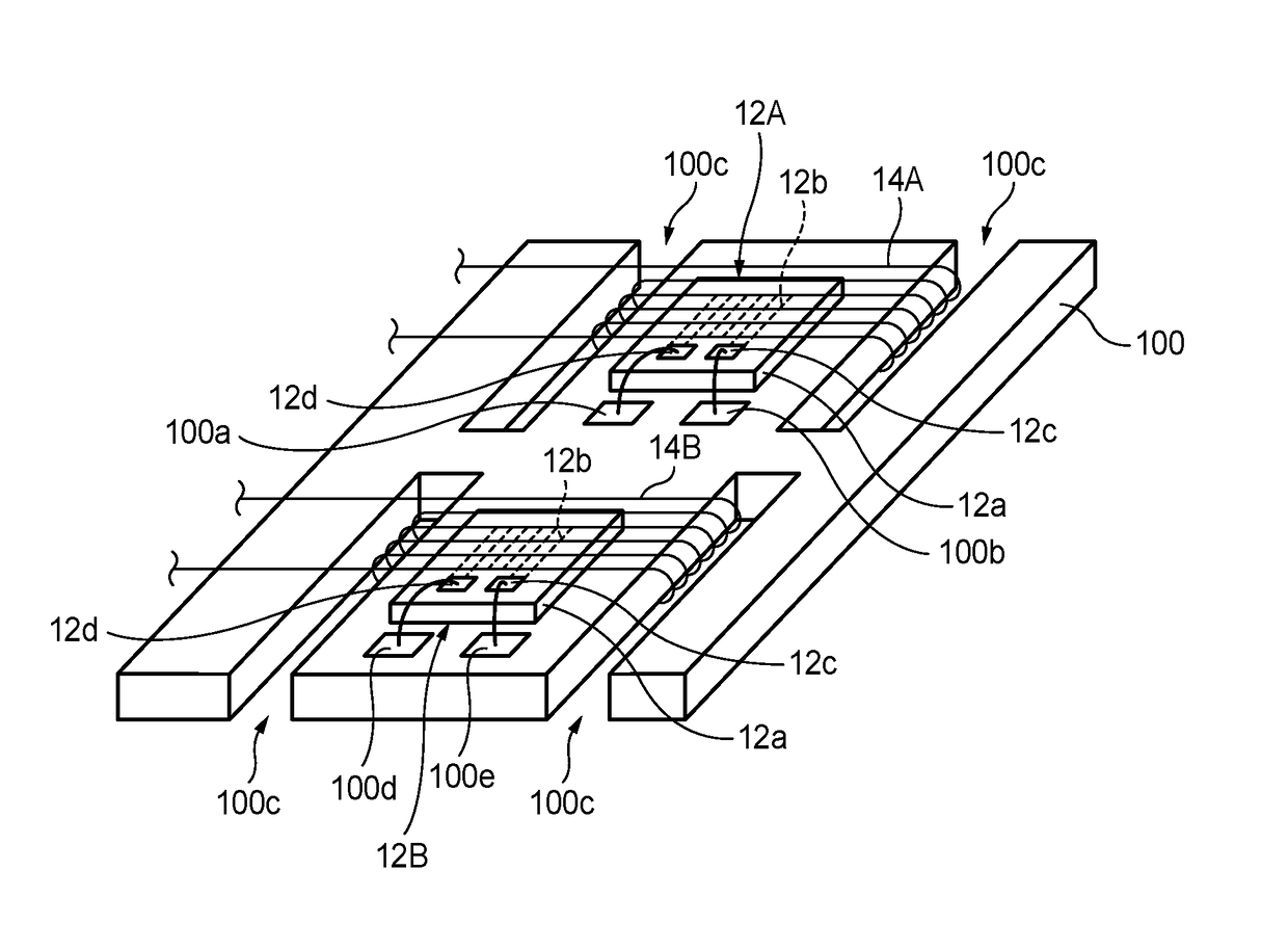
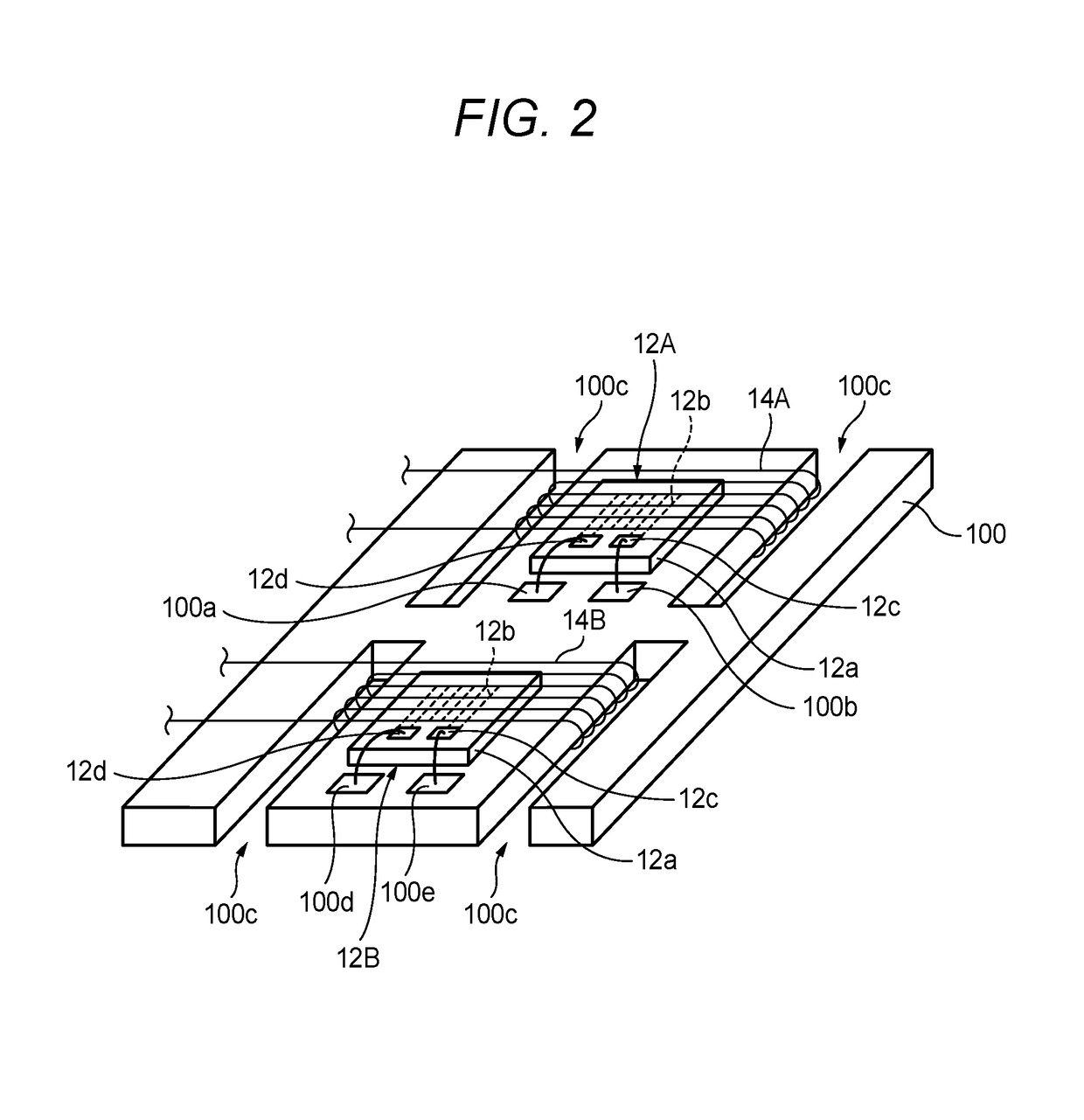
[0049]The magnetic field detection sensor 200 shown in FIG. 1 is composed of a drive unit 20 and a detection unit 30. As described later in detail, each of magnetoimpedance elements 12A and 12B which are included in the drive unit 20 includes a magnetic member that exhibits the magnetoimpedance effect. The magnetic field detection sensor 200 detects an external magnetic field utilizing the two magnetoimpedance elements 12A and 12B.

[0050]The two magnetoimpedance elements 12A and 12B have different magnetism detection characteristics. More specifically, the magnetoimpedance element 12A has relatively high sensitivity and the magnetoimpedance element 12B has low sensitivity. That is, whereas the magnetoimpedance element 12A can detect a relat...


PUM


Abstract

Magnetic members of a high-sensitivity magnetoimpedance element and a low-sensitivity magnetoimpedance element are connected to each other in series, and the strength and direction of an external magnetic field is detected on the basis of an impedance variation of this series circuit. The output of a magnetic field detection sensor mainly reflects an impedance variation of the high-sensitivity magnetoimpedance element in a weak magnetic field range, and mainly reflects an impedance variation of the low-sensitivity magnetoimpedance element in a strong magnetic field range, whereby continuous detection is enabled in a wide range from a weak magnetic field to a strong magnetic field.

Description

CROSS REFERENCE TO RELATED APPLICATIONS[0001]This application is based on and claims priority from Japanese patent application No. 2017-094911 filed on May 11, 2017, the entire contents of which are incorporated herein by reference.BACKGROUND OF THE INVENTION1. Technical Field[0002]The present invention relates to a magnetic field detection sensor that utilizes the magnetoimpedance effect.2. Background Art[0003]For example, Patent documents JP-A-9-127218, JP-A-2000-180521, and JP-A-2015-92144 disclose conventional techniques relating to a magnetic sensor using a magnetism detection element (MI element) that utilizes the magnetoimpedance effect. The impedance of a high-permeability alloy magnetic body such as an amorphous alloy wire varies sensitively according to an external magnetic field due to the skin effect. This phenomenon is the magnetoimpedance effect.[0004]In the configuration disclosed in Patent document JP-A-9-127218, an MI element is incorporated in a Colpitts oscillator...

Claims


Application Information

Patent Timeline
IPC IPC(8): G01R33/06
CPCG01R33/063
Inventor TANIGAWA, JUNYASUGIYAMA, HIROKIISHII, MAKOTO
Owner YAZAKI CORP
Learn More