Supercharge Your Innovation With Domain-Expert AI Agents!

Color filter substrate and liquid crystal display

a color filter substrate and liquid crystal display technology, applied in non-linear optics, instruments, optics, etc., can solve the problems of losing the advantages of system power efficiency of lcds when compared to oleds, the brightness of the pixels of an lcd cannot be controlled by adjusting an individually pixel, and the backlight unit's power consumption is about 80% of the full power consumption of the display panel. achieve the effect of improving the color filter substrate and improving the display

Active Publication Date: 2018-11-15
WUHAN CHINA STAR OPTOELECTRONICS TECH CO LTD
View PDF1 Cites 4 Cited by
  • Summary
  • Abstract
  • Description
  • Claims
  • Application Information

AI Technical Summary

Benefits of technology

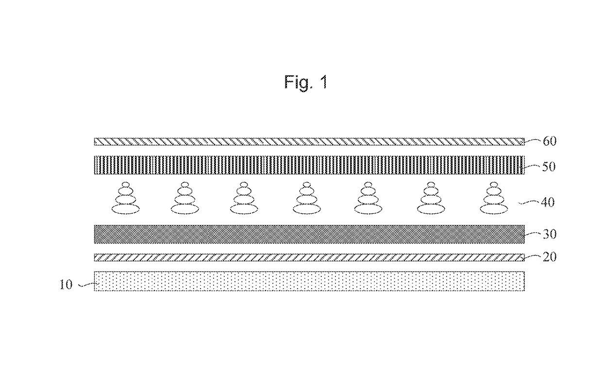
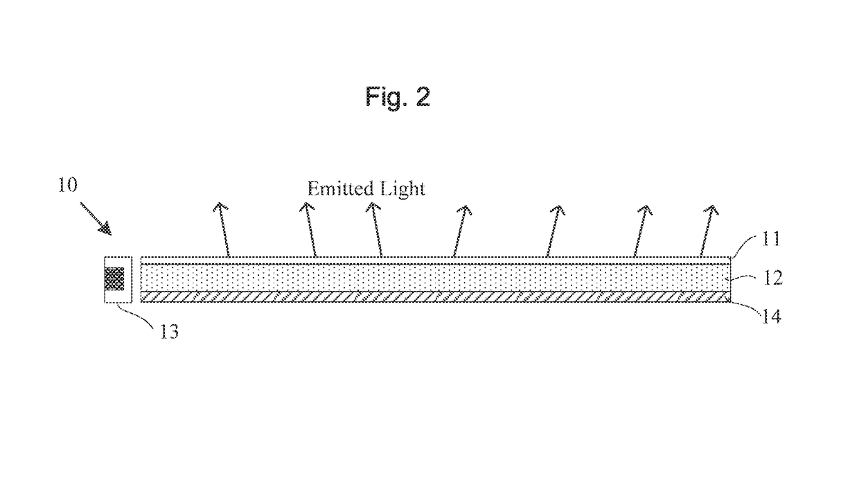
The present invention provides an improved color filter substrate and liquid crystal display. The color filter substrate includes a substrate, a light shielding array, and a plurality of color resist units. The light shielding array includes a plurality of light reflecting units and a plurality of light absorbing units. The light reflecting units reflect light, while the light absorbing units absorb light. This design allows for recycling of light emitted from the backlight module and increases the usage rate of the backlight resources. Overall, the invention saves energy and resources.

Problems solved by technology

However, when compared to the self-illuminating OLED display technologies, brightness of the pixels of an LCD cannot be controlled by adjusting an individually pixel.
Power consumption of the backlight unit is about 80% of the full power consumption of the display of the entire display panel.
However, over 90% of light is blocked or absorbed instead of being contributed to the brightness of the display, which causes the LCDs to lose advantages of system power efficiency when compared to OLEDs.
However, the metal electrodes of the array substrate are hard to replace with transparent electrodes with high resistance rate.
Therefore, the conventional technologies are defective and need improvement urgently.

Method used


Image

  • Color filter substrate and liquid crystal display
  • Color filter substrate and liquid crystal display
  • Color filter substrate and liquid crystal display

Examples


Embodiment Construction

[0041]The following descriptions for embodiments refer to the accompanied figures for illustrating specific embodiments to which the present invention is applied. Directional terminologies mentioned by the present invention, for example “upper”, “lower”, “front”, “rear”, “left”, “right”, “inner”, “outer”, “side”, etc. only refer to directions of figures. Therefore, the used directional terminologies are for explanation and understanding of the present invention instead of limiting the present invention.

[0042]In the figures, modules similar in structures are marked with identical reference numeral.

[0043]Furthermore, terminologies “first”, “second” are merely used for purposes of description instead of being understood as an indication or implication of comparative importance or the number of the feature referred to. therefore, the feature limited by “first” or “second” may indicate or imply one or more of such feature. In the description of the present invention, unless an explanatio...


PUM

PropertyMeasurementUnit
thicknessaaaaaaaaaa
reflectionaaaaaaaaaa
brightnessaaaaaaaaaa

Abstract

A color filter substrate and a liquid crystal display are provided. The color filter substrate has a substrate, a light shielding array and a plurality of color resist units. A projection of the light shielding array on the substrate and a projection of the color resist units on the substrate are connected to each other without intersecting each other. The light shielding array has a plurality of light reflecting units and a plurality of light absorbing units. The light reflecting units are configured to reflect light and are disposed on disposed above the substrate, and the light absorbing units are configured to absorb light and disposed on the light reflecting units.

Description

FIELD OF THE INVENTION[0001]The present invention relates to the field of liquid crystal display panels, especially to a color filter substrate and liquid crystal display.BACKGROUND OF THE INVENTION[0002]In modern society reliance on information, the importance of displays as a medium for information transmission is further increased. To have a leading status in the future, displays are developed consistent with the trends of being lighter, thinner, and lower power consuming, more inexpensive, and having better graphic quality.[0003]Core display technologies is to reproduce human eye perception to the real world. Mainstream display technologies comprise the liquid crystal display (LCD) and organic light-emitting diode (OLED) has different advantages in color reduction, viewing angle, contrast, brightness and darkness dynamic range control and reliability. LCD display technologies have longer development history and have advantages of mature manufacturing processes, lower cost, and h...

Claims


Application Information

Patent Timeline
Patent Type & Authority Applications(United States)
IPC IPC(8): G02F1/1335
CPCG02F1/133528G02F1/133512G02F1/133553G02F2001/133357G02F1/133514G02F1/133357
Inventor ZHA, GUOWEI
Owner WUHAN CHINA STAR OPTOELECTRONICS TECH CO LTD
Features
  • R&D
  • Intellectual Property
  • Life Sciences
  • Materials
  • Tech Scout
  • Unparalleled Data Quality
  • Higher Quality Content
  • 60% Fewer Hallucinations
Learn More