Cassegrain antenna for equalizing orbital angular momentum mode tranmission loss

a technology of angular momentum and antenna, applied in the field of antenna, can solve the problems of low signal to interference noise ratio (sinr), difficult to recover data, and difficult to selectively detect a specific oam component at the receiving end, so as to reduce the difference of transmission loss or transmission gain, reduce the difference of transmission loss of higher-order mode beams, and detect beams easily

Inactive Publication Date: 2018-11-15
ELECTRONICS & TELECOMM RES INST
View PDF1 Cites 8 Cited by
  • Summary
  • Abstract
  • Description
  • Claims
  • Application Information

AI Technical Summary

Benefits of technology

[0006]Accordingly, embodiments of the present disclosure provide an antenna and a signal transmission method using the antenna, which can reduce differences in transmission losses between beams having different OAM modes by controlling antenna gains of the beams according to the OAM modes of the beams.
[0019]Using to the embodiments according to the present disclosure, it is made possible to easily detect a beam having a specific OAM at the receiving end by reducing the differences of transmission losses or transmission gains between the zeroth order mode beam and the higher order mode beams. Also, by reducing the transmission loss of the higher order mode beams, the signal-to-noise ratio (SNR) of the higher order mode beams can be increased.

Problems solved by technology

There is a problem in that it is difficult to selectively detect a specific OAM component at the receiving end if the difference between the reception intensities of the beams according to the OAM modes exceeds a certain level.
Also, even when the OAM component having a small reception intensity is detected at the receiving end, the signal to interference and noise ratio (SINR) is low, and thus it may be difficult to recover the data.

Method used


Image

  • Cassegrain antenna for equalizing orbital angular momentum mode tranmission loss
  • Cassegrain antenna for equalizing orbital angular momentum mode tranmission loss
  • Cassegrain antenna for equalizing orbital angular momentum mode tranmission loss

Examples


first embodiment

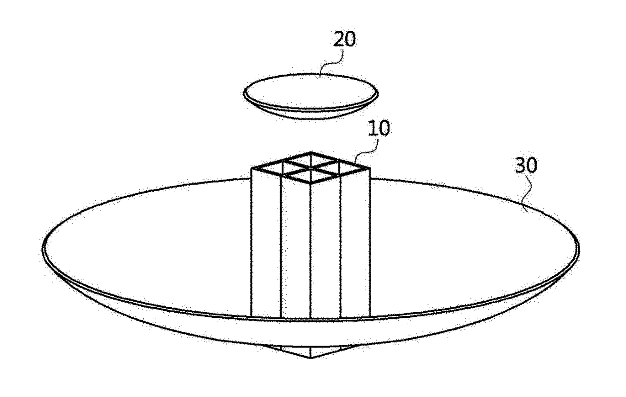
[0065]FIG. 8 is a perspective view of an antenna according to the present disclosure.

[0066]Referring to FIG. 8, an antenna may include a radiator 110 for emitting beams. The radiator 110 may include a plurality of emitters 110a, 110b, 110c, and 110d. The OAMs of the beams emitted by the radiator 110 may be determined by phase differences between the beams emitted by the plurality of emitters 110a, 110b, 110c, and 110d. For example, when the radiator 110 emits zeroth order OAM mode beams, the emitters 110a, 110b, 110c, and 110d may emit beams in the same phase. As another example, when the radiator 110 emits 1st order mode beams, the emitters 110a, 110b, 110c, and 110d may emit beams in different phases. The phase of the beam emitted by the second emitter 110b and the phase of the beam emitted by the first emitter 110a may differ by (±π / 2). The phase of the beam emitted by the third emitter 110c and the phase of the beam emitted by the first emitter 110a may differ by (±π). The phase...

second embodiment

[0083]FIG. 15 is a conceptual view illustrating a cross-section of an antenna and traveling directions of higher-order mode beams according to the present disclosure.

[0084]Referring to FIG. 15, the reflective surface of the main-reflector 130 may have a shape of a trace formed by rotating a curve similarly to the reflective surface of the sub-reflector 120. The reflective surface of the main-reflector 130 may have a shape in which a curve is rotated around a rotation axis spaced apart from a vertex of the curve. In this case, the transmission loss of the higher order mode beams can be reduced. Also, the transmission loss of the zeroth order mode beams can be larger than the conventional one.

[0085]FIG. 16 is a graph illustrating antenna gains when zeroth order mode beams are radiated using the conventional antenna shown in FIG. 4. Referring to FIG. 16, a main lobe gain of the zeroth order mode beam may be 28.7 dB. Also, FIG. 17 is a graph illustrating antenna gains when 1st order mod...


PUM


Abstract

Disclosed is a Cassegrain-type antenna. The Cassegrain-type antenna may comprise a main-reflector; a sub-reflector; and a radiator radiating beams by using a plurality of emitters. Also, a reflective surface of the sub-reflector has a shape of a trace formed by rotating a first curve having a vertex and being convex toward the main-reflector around a rotation axis spaced apart from the vertex.

Description

CROSS-REFERENCE TO RELATED APPLICATIONS[0001]This application claims priority to Korean Patent Application No. 10-2017-0059802 filed on May 15, 2017 in the Korean Intellectual Property Office (KIPO), the entire contents of which are hereby incorporated by reference.BACKGROUNDTechnical Field[0002]The present disclosure relates to an antenna, and more specifically, to an antenna capable of reducing differences in transmission losses between beams having different orbital angular momentum (OAM) modes.Related Art[0003]As mobile communication devices are being spread, the number of Internet accesses through mobile devices surpassed the number of Internet accesses through personal computers, and most of the Internet accesses are currently being generated by the mobile devices. As the wireless communication environment is activated, the traffic volume of smart phones is steadily increasing. Accordingly, various technologies that can increase the communication capacity have been developed.[...

Claims


Application Information

Patent Timeline
Patent Type & Authority Applications(United States)
IPC IPC(8): H01Q19/19
CPCH01Q19/191H01Q25/007H01Q19/19H01Q3/26H01Q15/14
Inventor LEE, WANG JOO
Owner ELECTRONICS & TELECOMM RES INST
Why Eureka
Try Eureka