
An injection device with a removable cap

Inactive Publication Date: 2018-11-22
NOVO NORDISK AS
View PDF24 Cites 1 Cited by
  • Summary
  • Abstract
  • Description
  • Claims
  • Application Information

AI Technical Summary

Benefits of technology

The invention aims to prevent the need for initial or general priming (air-shots between injections) of the injection device by providing a mechanism that limits axial movement of the plunger in the proximal direction and allows movement in the distal direction, in combination with an air-tight chamber. This reduces the need for priming, resulting in more efficient and effective injection.

Problems solved by technology

Since the injection device is discarded after one use only, the sterility barrier is designed such that once it has been broken the needle cover cannot be mounted again to re-establish the air-tight chamber.
However, should a user decide to maintain the needle assembly attached to the injection device during storage there is a risk that the liquid drug inside the lumen of the needle cannula will dry out between injections and thereby clog the free passage through the lumen.
The same problem also occurs when using a so-called durable injection device wherein the user is able to change the cartridge.
Even if the distal end of the injection device, being pre-filled or durable, is covered by an ordinary removable protective cap between injections clogging due to dried out liquid drug in the lumen of the needle cannula is still a problem.
However, since many people choose to leave the used needle assembly attached to the injection device after an injection has been performed and during storage clogging of the needle cannula is a problem for many people.
Air in the cartridge may result in a too small a dose of the liquid drug being delivered since some of the ejected volume consists of the trapped air.
A clogged needle cannula may occur if an injection device with an attached needle cannula is subjected to heat (and especially to dry heat) since parts of the liquid drug located in the lumen of the needle cannula will evaporate leaving residual elements potentially clogging the lumen of the needle cannula partly or fully.
However, it is a concern that not all users properly prime their injection devices every time they should and hence do not fully follow the instructions for use, and it is also known that not all users are fully aware of the reasons and importance of priming their injection device.
However, not all users remove the needle assembly after use, but rather keep it mounted on the injection device.
When an injection device is subjected to a higher temperature, e.g. by being removed from a refrigerator, the liquid drug in the cartridge will expand and it will likely leak out of the needle cannula.
These adverse effects will be increased by repeated temperature increases and decreases as happening when a user repeatedly uses an injection device and stores it with the needle cannula attached e.g. in a refrigerator between injections.
This may cause the plunger inside the cartridge to move out of its abutment with the piston rod and thus create an air gap between the plunger and the piston rod (or the piston rod foot if such is used).
However, many of these solutions add complexity and costs to the injection device and some may also add additional length to the injection device.

Method used


Image

  • An injection device with a removable cap
  • An injection device with a removable cap
  • An injection device with a removable cap

Examples


example a

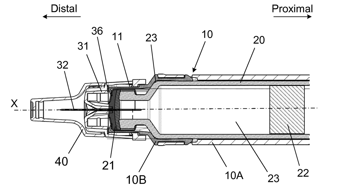
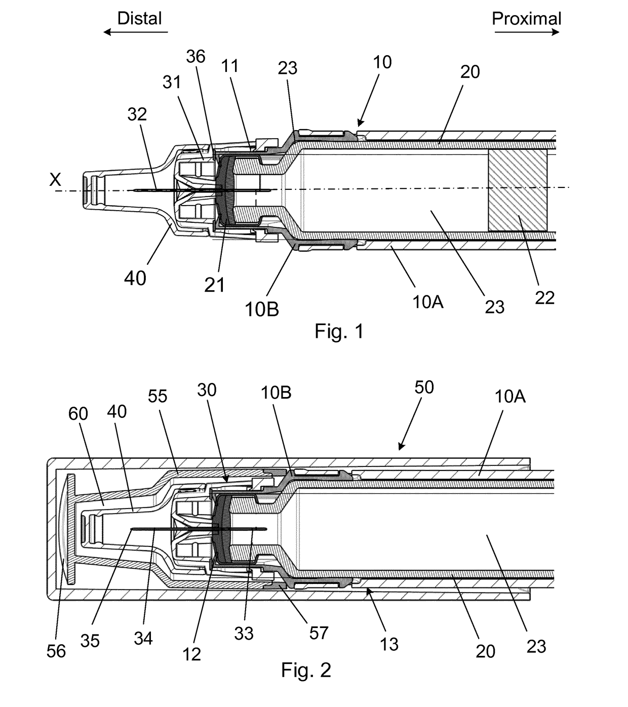
[0058]An injection device for injecting a plurality of doses of a liquid drug through a number of injections, the injection device comprising:

a housing assembly supporting a cartridge, at least in use, which cartridge has a distal end sealed by a pierceable septum and a proximal end sealed by a movable plunger defining an interior containing the liquid drug,

a piston rod for moving the movable plunger distally inside the cartridge,

a removable protective cap assembly removable coupled to the housing assembly and surrounding at least a distal end of the housing assembly between injections, and

a needle mount, at least in use, carrying a needle assembly comprising a needle cannula secured in a needle hub which needle cannula has a proximal end in liquid communication with the interior of the cartridge and a distal end with a distal tip for penetrating the skin of a user.

[0059]The injection device is further characterized in that the removable protective cap assembly surrounds at least th...

example b

[0061]An injection device according to example A), wherein the housing assembly) distally is provided with a radial flange against which flange both the needle hub and the cartridge abuts.

example c

[0062]An injection device according to any of the examples A) or B), wherein the air-tight seal is provided on an inner surface of the removable protective cap assembly.


PUM


Abstract

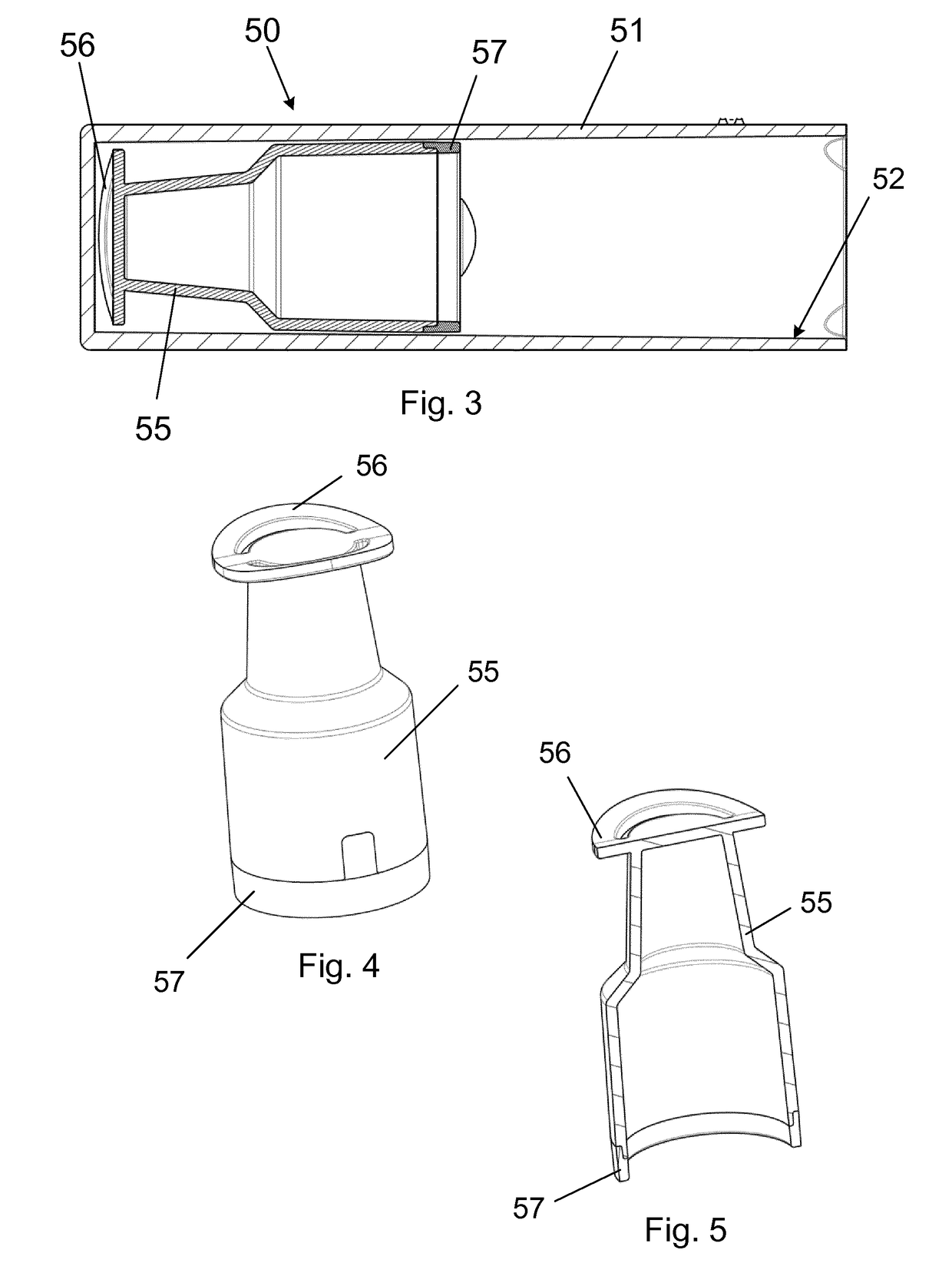
The present invention relates to an injection device for delivering a plurality of doses of a liquid drug. The injection device comprises a housing assembly (10,110,210) and a needle mount (11,111,211) securing a needle cannula (32,132,232). The distal end of the housing assembly is covered by a removable protective cap assembly (50,150,250) when not in use. The protective cap assembly also surrounds a distal tip of the needle cannula and is operational sealed against the housing assembly with an air-tight seal such that an air-tight chamber (60,160,260) is established around the distal tip of the needle cannula between injections.

Description

THE TECHNICAL FIELD OF THE INVENTION[0001]The invention relates to an injection device for delivering a plurality of doses of a liquid drug through a number of injections and especially to an injection device wherein the distal end of the housing of the injection device is protected by a removable protective cap between injections. The injection device may be of the automatic type in which a drive member during dose ejection is rotated by a torsion spring to move a piston rod forward inside a cartridge but it may also be of other types not utilising any spring at all or using some other type of spring in a different way.DESCRIPTION OF RELATED ART[0002]US 2003 / 0144633 disclose a needle assembly in which the distal end of the needle cannula is located inside an air-tight chamber. The air-tight chamber is provided between a needle cover and the needle hub wherein a sealing element also is provided. The sealing element forms a sterility barrier maintaining the distal end of the needle c...

Claims


Application Information

Patent Timeline
IPC IPC(8): A61M5/162
CPCA61M5/162A61M5/24A61M5/3202A61M2005/2403
Inventor ROERVIG, SIMONJAKOBSEN, NIKOLAJ EUSEBIUSHANSEN, STEFFEN
Owner NOVO NORDISK AS
Learn More