Vehicle Having a Load Carrying Deck and Attachment Device for the Same

a technology for vehicles and cargo vehicles, which is applied in the direction of vehicular safety arrangments, bumpers, transportation items, etc., can solve the problems of increasing the necessary cost, increasing the difficulty of mounting the load, and increasing the cost of the extension member of the cargo vehicle under the storage postur

Active Publication Date: 2018-11-22
KUBOTA LTD
View PDF0 Cites 5 Cited by
  • Summary
  • Abstract
  • Description
  • Claims
  • Application Information

AI Technical Summary

Benefits of technology

[0057]wherein the connecting screw is operable between a fastening state in which the first attaching member and the second attaching member are fastened to the guide rail portion for clamping the guide rail portion by the first attaching member and the second attaching member, thereby to fix the supporting portion to the side gate; and a fastening released state in which fastening of the first attaching member and the second attaching member to the guide rail portion is released, thus allowing sliding of the first attaching member and the second attaching member, thereby to allow sliding of the supporting portion relative to the side gate.

Problems solved by technology

Further, when it is desired to change the retaining portion formed in the gate to one having a different specification, such as its shape, structure or function, this will require replacement of the entire attachment device, thus increasing the necessary cost.
Thus, depending on length or size of a load to be mounted on the deck, the deck extension member under the storage posture will become an obstacle.
So that, as the end of the load may ride on this load extension member, thus being inclined or one end of the load may hit the load extension member, so that the other end of the load projects from the deck, thus making mounting of the load difficult.

Method used


Image

  • Vehicle Having a Load Carrying Deck and Attachment Device for the Same
  • Vehicle Having a Load Carrying Deck and Attachment Device for the Same
  • Vehicle Having a Load Carrying Deck and Attachment Device for the Same

Examples


first embodiment

[0084]Front-rear direction and right-left direction in the embodiments of the invention are defined as follows, unless explicitly indicated otherwise. Namely, a traveling direction in forward traveling is the “front”, and a traveling direction in reverse traveling is the “rear”. Further, relative to a front facing posture in the front-rear direction, the direction corresponding to the right side is “right” and the direction corresponding to the left side is “left”, respectively.

[General Arrangement of Multi-Purpose Vehicle]

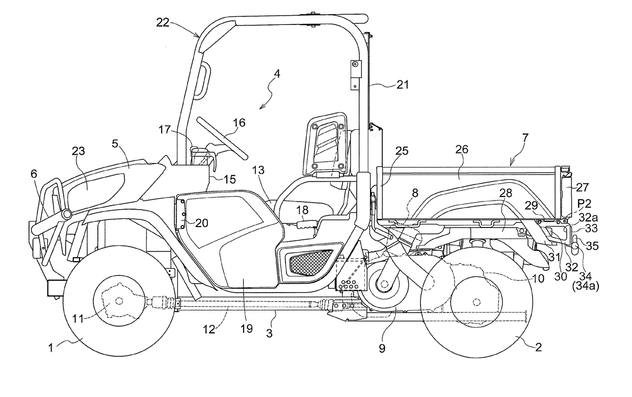
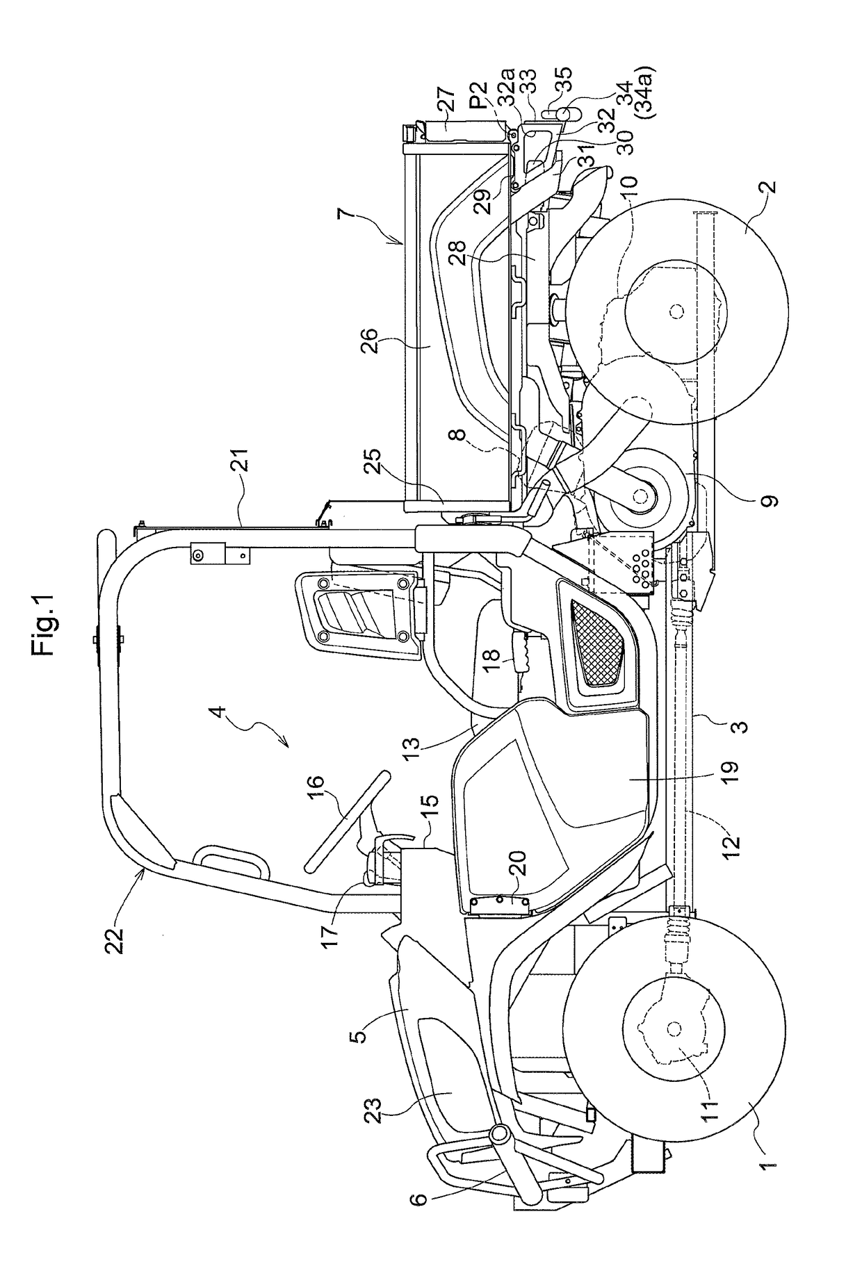
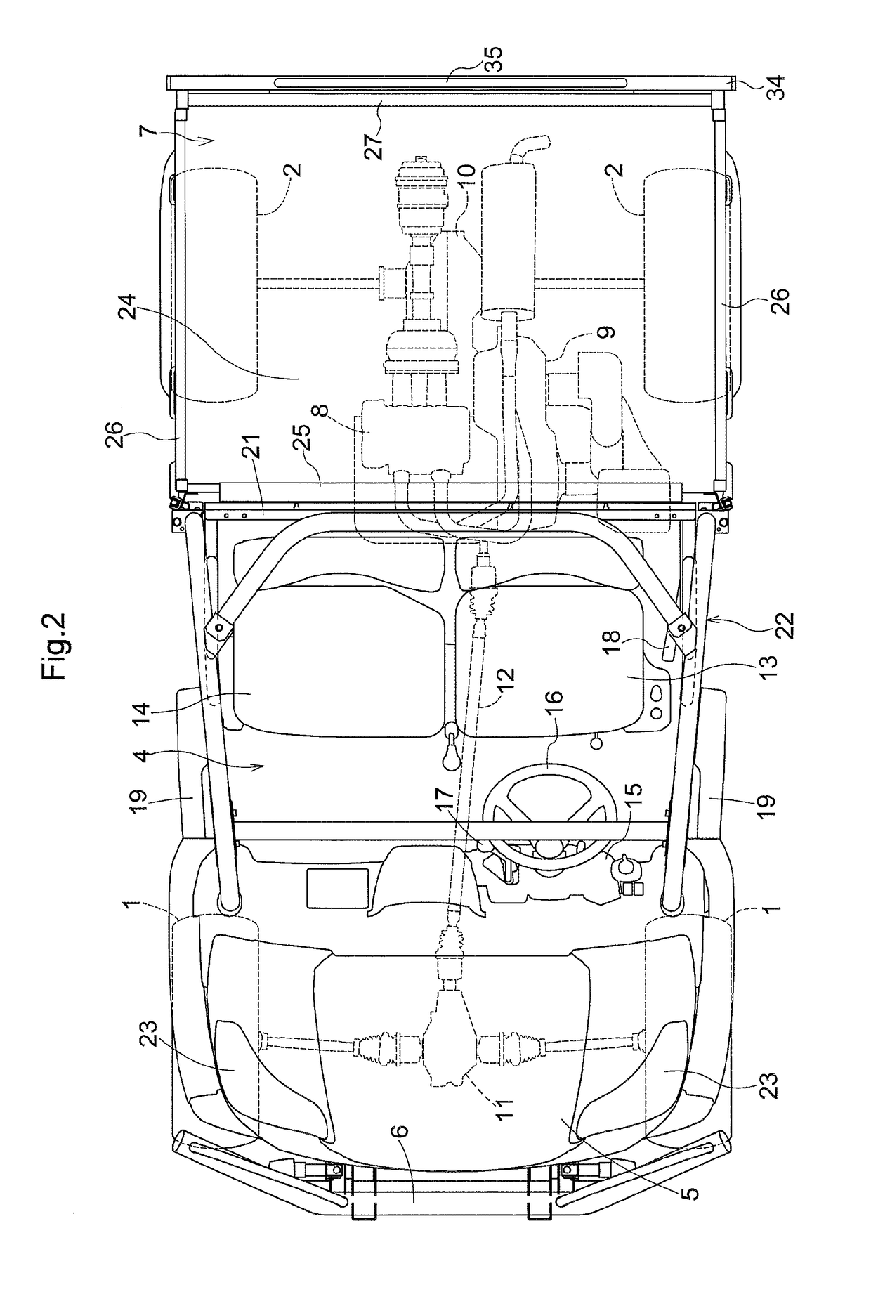
[0085]FIG. 1 and FIG. 2 show a multi-purpose vehicle in its entirety. At front portion of a vehicle body frame 3, right and left front wheels 1 are supported. At a rear portion of the vehicle body frame 3, right and left rear wheels 2 are supported. In the vehicle body frame 3, a driving section 4 is provided between the front wheels 1 and the rear wheels 2. On the front side of the driving section 4, a hood 5 and a front bumper 6 are provided. The hood 5 mounts r...

modified embodiments of first embodiment

[0105](1) The tail lamp 30 can be attached not to the load carrying deck 7, but to certain vehicle body portions such as the supporting frames 28, thus being disposed on the lower side of the right and left portions of the rear portion of the load carrying deck 7.

[0106](2) The rear bumper 34 can be connected not to / between the lower portion of the right and left tail lamp guards 33, but to / between portions slightly upwards from the lower portions of the right and left tail lamp guards 33.

[0107](3) The tail lamp guards 33 can be connected not to the pivot members 29, but to the bottom plate portion 24 of the load carrying deck 7.

[0108](4) A seat or seats (not shown) can be provided on the rear side of the driver's seat 13 and the auxiliary seat 14.

second embodiment

[0109]Next, a second embodiment will be explained.

[0110]FIG. 5 is a side view showing an entire utility vehicle (a multi-purpose vehicle) as one example of a vehicle having a load carrying deck. A direction of “F” shown in FIG. 5 is defined as the front direction of a traveling vehicle body 101, a direction of “B” is defined as the rear direction of the traveling vehicle body 101, a direction on the near side in the view is defined as the left direction of the traveling vehicle body 101 and a direction on the far side in the view is defined as the right direction of the traveling vehicle body 101, respectively.

[Configuration of Utility Vehicle]

[0111]As shown in FIG. 5, the utility vehicle includes the traveling vehicle body 101 mounting a pair of right and left front wheels 102 which are drivable and steerable and a pair of right and left rear wheels 103 which are drivable. At a front portion of the traveling vehicle body 101, a driving section 104 is formed. In this driving section...


PUM


Abstract

A multi-purpose vehicle includes a seat provided between front wheels and rear wheels, a load carrying deck provided on a rear side of the seat, a right tail lamp provided on a right lower side of a rear portion of the load carrying deck, a left tail lamp provided on a left lower side of the rear portion of the load carrying deck, a right tail lamp guard provided on rear side of the right tail lamp and connected to the load carrying deck, a left tail lamp guard provided on rear side of the left tail lamp and connected to the load carrying deck, and a rear bumper. The rear bumper is connected to and between the right tail lamp guard and the left tail lamp guard.

Description

CROSS-REFERENCE TO RELATED APPLICATIONS[0001]This application claims priority to Japanese Patent Applications No. 2017-99053, filed May 18, 2017, No. 2017-109385, filed Jun. 1, 2017 and No. 2017-111965, filed Jun. 6, 2017, the disclosures of which are hereby incorporated in their entirety by reference.BACKGROUND OF THE INVENTION1. Field of the Invention[0002]The present invention relates to a vehicle having a load carrying deck and relates also to an attachment device for such vehicle having a load carrying deck.2. Description of Related Art(1) First Related Art[0003]JP 2011-116318 A (or US 2011 / 0132678 A1 corresponding thereto) discloses a multi-purpose vehicle for use in transport of persons, transport of load, a recreational activity, etc. In the multi-purpose vehicle, a seat is provided between front wheels and rear wheels and a load carrying deck is mounted on the rear side of the seat; and a headlight and a front bumper are provided at front portions of the vehicle body.[0004]...

Claims


Application Information

Patent Timeline
Patent Type & Authority Applications(United States)
IPC IPC(8): B62D33/03B62D33/08B62D21/18B60Q1/30B60Q1/00B60R19/02B60P7/08
CPCB62D33/03B62D33/08B62D21/183B60Q1/30B60Q1/0005B60R19/023B60P7/0807B60P3/42B60Q1/0035B62D23/005B62D33/02B60Q2800/20
Inventor UENO, SATOKOKURAMOTO, TAKASHIFUJIWARA, JUNICHISASAKI, WATARU
Owner KUBOTA LTD
Why Eureka
Try Eureka