A System for Monitoring a Maritime Environment

a monitoring system and maritime environment technology, applied in the field of objects detection in maritime environments, can solve the problems of coarse mitigation, limited coverage, and limited resolution of objects in maritime environments, and achieve the effect of efficiently determining the movement characteristic of objects and efficiently visualizing the location of objects

Active Publication Date: 2018-11-22
MARITIME RADAR SYST +1
View PDF9 Cites 7 Cited by
  • Summary
  • Abstract
  • Description
  • Claims
  • Application Information

AI Technical Summary

Benefits of technology

[0029]According to an implementation form, the processing device is configured to determine a speed, an acceleration, or a heading of the object in the maritime environment upon the basis of the plurality of sensor signals. Thus, a movement characteristic of the object can be determined efficiently. Movement characteristics may only be one of several characteristics which can be recognized by the processing. Object or meteorological or oceanographic (MetOcean)characteristics, e.g. representing the backscatter of the object or the ocean, can be used for its characterization, e.g. object shape characteristics.
[0030]According to an implementation form, the processing device is configured to determine the location of the object in the maritime environment within a 3-dimensional Cartesian coordinate system. Thus, the location of the object can be visualized efficiently.

Problems solved by technology

Due to limitations of stand-alone radio detection and ranging devices, e.g. a limited bandwidth or limited aperture, object detection in maritime environments suffers from a limited resolution of object detection and a coarse mitigation of sea clutter.
Furthermore, no simultaneous full coverage around the maritime vessel and only a limited coverage in close areas around the maritime vessel may be provided.

Method used


Image

  • A System for Monitoring a Maritime Environment
  • A System for Monitoring a Maritime Environment
  • A System for Monitoring a Maritime Environment

Examples


Embodiment Construction

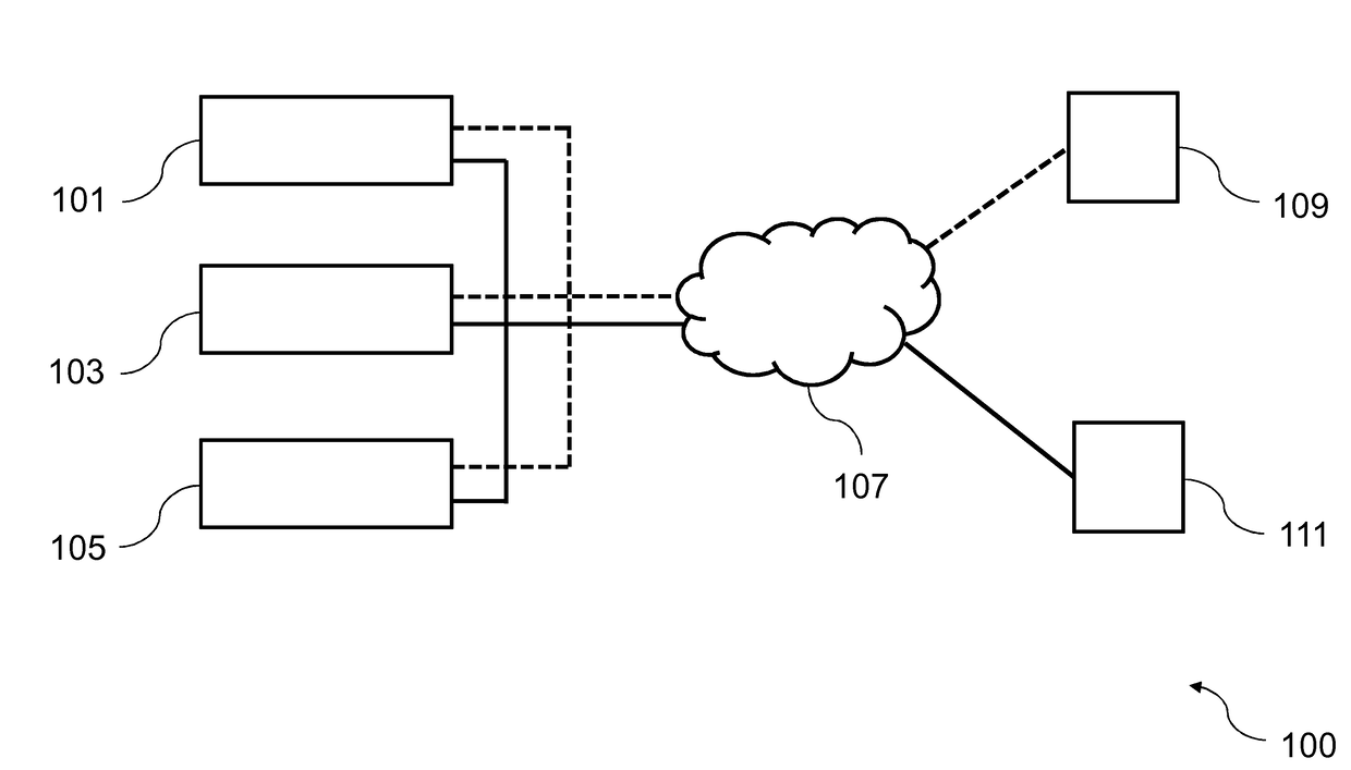
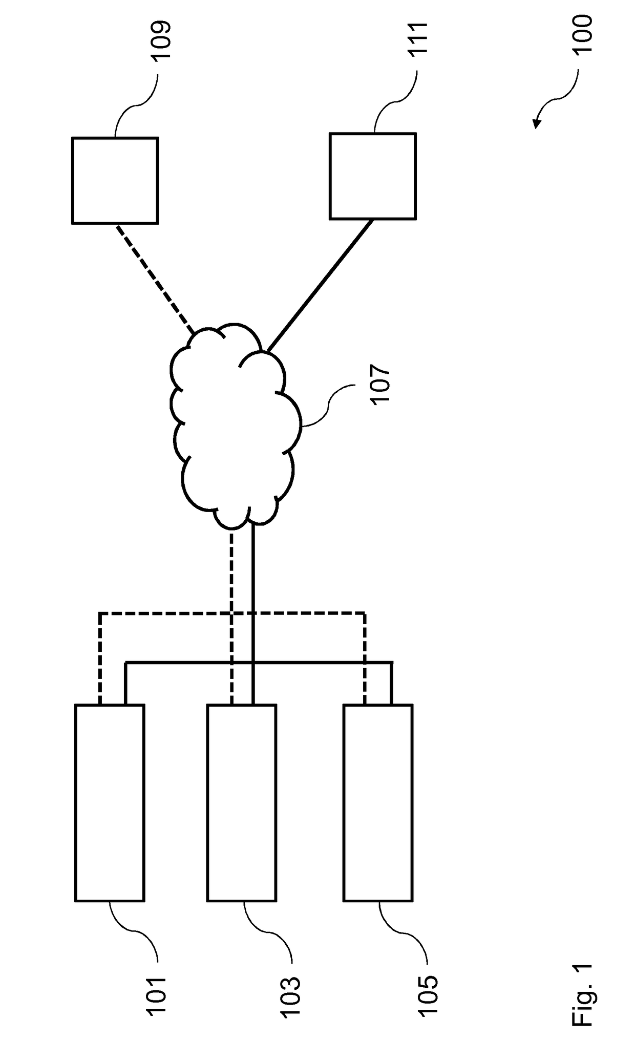
[0063]FIG. 1 shows a diagram of a system 100 for monitoring a maritime environment according to an implementation form.

[0064]The system 100 comprises a plurality of radio detection and ranging devices 101, 103, 105 being configured to perform a synchronous detection of an object in the maritime environment, to transmit a plurality of sensor signals respectively relating to a location of the object in the maritime environment over a communication network 107, and to receive a synchronization signal, each radio detection and ranging device 101, 103, 105 being configured to synchronize its operation according to the synchronization signal, a synchronization source 109 being configured to generate the synchronization signal for synchronizing operations of the plurality of radio detection and ranging devices 101, 103, 105, and to provide the synchronization signal over the communication network 107 to the plurality of radio detection and ranging devices 101, 103, 105, and a processing de...


PUM


Abstract

A system for monitoring a maritime environment comprises a plurality of radio detection and ranging devices configured to perform a synchronous detection of a maritime environment object, to transmit a plurality of sensor signals respectively relating to a location of the maritime environment object over a communication network, and to receive a synchronization signal. Each radio detection and ranging device is configured to synchronize its operation according to the synchronization signal. A synchronization source is configured to generate the synchronization signal for synchronizing operations of radio detection and ranging devices, and to provide the synchronization signal over the communication network to the radio detection and ranging devices. A processing device is configured to receive the plurality of sensor signals from the plurality of radio detection and ranging devices, and to determine the location of the object in the maritime environment upon the basis of the plurality of sensor signals.

Description

TECHNICAL FIELD[0001]The invention relates to the field of object detection in maritime environments.BACKGROUND OF THE INVENTION[0002]A detection of objects in maritime environments can be performed by different detection devices such as radio detection and ranging (radar) devices or sound navigation and ranging (sonar) devices. Radio detection and ranging devices may e.g. be adapted to monitor the maritime environment over long ranges on the water surface whereas sound navigation and ranging devices may e.g. be adapted to monitor the maritime environment at short ranges under the water surface.[0003]Typical radio detection and ranging devices to be used in maritime environments operate as stand-alone devices in the X frequency band (8-12 GHz) or S frequency band (2-4 GHz). In a maritime vessel, typical radio detection and ranging devices may e.g. be arranged at a bow or a stern of the maritime vessel.[0004]Due to limitations of stand-alone radio detection and ranging devices, e.g. ...

Claims


Application Information

Patent Timeline
Patent Type & Authority Applications(United States)
IPC IPC(8): G06F19/00G01S5/02G01S13/937
CPCG01S5/02G06F19/00G01S7/003G01S7/415G01S13/56G01S13/86G01S13/87G01S13/88G01S13/956G01S7/40G01S13/937Y02A90/10G01S7/4039G01S13/06G01S13/505G01S13/878
Inventor DOKKEN, SVERREBOS, ANDREGRUSZKA, JACEK
Owner MARITIME RADAR SYST
Why Eureka
Try Eureka