Liquid droplet forming device, dispensing device, and method of preparing base material

Active Publication Date: 2018-11-29
RICOH KK
View PDF17 Cites 7 Cited by
  • Summary
  • Abstract
  • Description
  • Claims
  • Application Information

AI Technical Summary

Benefits of technology

The patent describes a device that can create liquid droplets with more accuracy. This device is able to detect the number of particles in the liquid droplet.

Problems solved by technology

The problem is that accuracy of detecting the number of particles included in the discharged liquid droplet is low because the number of the particles included in the liquid droplet immediately prior to flying may be or may not be equal to the number of the particles included in the flying liquid droplet.

Method used


Image

  • Liquid droplet forming device, dispensing device, and method of preparing base material
  • Liquid droplet forming device, dispensing device, and method of preparing base material
  • Liquid droplet forming device, dispensing device, and method of preparing base material

Examples


first embodiment

[0032][Structure of the Liquid Droplet Forming Device]

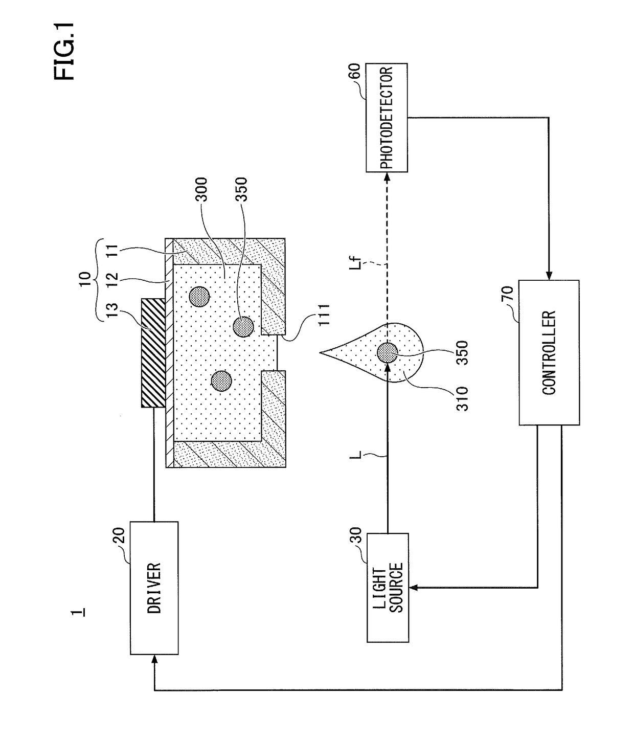
[0033]First, a liquid droplet forming device according to a first embodiment is described. FIG. 1 is a schematic diagram exemplifying the liquid droplet forming device according to the first embodiment. Referring to FIG. 1, the liquid droplet forming device 1 includes a liquid droplet discharger 10; a driver 20; a light source 30; a photodetector 60; and a controller 70.

[0034]The droplet discharger is not particularly limited; however, there are an inkjet head based on a piezoelectric pressure method using a piezoelectric element, an inkjet head based on a thermal method using a heater, an inkjet head based on an electrostatic method such that a liquid is pulled by electrostatic attraction, etc. Among these, the piezoelectric pressure method is favorable in that damage on fluorescent particles 350 by heat or an electric field is relatively small.

[0035]The liquid droplet discharger 10 includes a liquid chamber 11, a membrane 12, a...

modified example 1

of the First Embodiment

[0064]In the modified example 1 of the first embodiment, an example of the liquid droplet forming device is illustrated in which the configuration of the part of detecting the fluorescence emitted by the fluorescent particles 350 is modified. Note that, in the modified example 1 of the first embodiment, the description of a component that is the same as that of the above-described embodiment may be omitted. FIG. 5 is a schematic diagram exemplifying the liquid droplet forming device according to the modified example 1 of the first embodiment. Referring to FIG. 5, the liquid droplet forming device 1A differs from the liquid droplet forming device 1 (see FIG. 1) in the point that a mirror 40 is provided in front of the photodetector 60.

[0065]As described above, in the liquid droplet forming device 1A, by arranging the mirror 40 in front of the photodetector 60, the degrees of freedom on the layout of the photodetector 60 can be enhanced.

[0066]For example, when t...

modified example 2

of the First Embodiment

[0068]In the modified example 2 of the first embodiment, another example of the liquid droplet forming device is illustrated in which the configuration of the part of detecting the fluorescence emitted by the fluorescent particles 350 is modified. Note that, in the modified example 2 of the first embodiment, the description of the component that is the same as that of the above-described embodiment may be omitted.

[0069]FIG. 6 is a schematic diagram exemplifying the liquid droplet forming device according to the second modified example of the first embodiment. Referring to FIG. 6, the liquid droplet forming device 1B differs from the liquid droplet forming device 1 (see FIG. 1) in the point that, in addition to the photodetector 60 for receiving the fluorescence Lf1 emitted from the fluorescent particles 350, a photodetector 61 for receiving the fluorescence Lf2 emitted from the fluorescent particles 350 is provided.

[0070]Here, the fluorescence Lf1 and the fluo...


PUM


Abstract

A liquid droplet forming device includes a liquid droplet discharger that discharges, as a liquid droplet, a particle suspension liquid in which one or more fluorescent particles are suspended; a light source for irradiating light onto the flying liquid droplet discharged from the liquid droplet discharger; a photodetector that receives fluorescence that is emitted by the one or more fluorescent particles included in the liquid droplet in response to the light as excitation light; and a particle number detector that detects a number of the one or more fluorescent particles included in the liquid droplet based on information from the photodetector.

Description

CROSS-REFERENCE TO RELATED APPLICATION[0001]The present application is a continuation application filed under 35 U.S.C. 111(a) claiming benefit under 35 U.S.C. 120 and 365(c) of PCT International Application No. PCT / JP2017 / 000735 filed on Jan. 12, 2017 and designating the U.S., which claims priority to Japanese Patent Application No. 2016-012260 filed on Jan. 26, 2016 and Japanese Patent Application No. 2016-176812 filed on Sep. 9, 2016. The entire contents of the foregoing applications are incorporated herein by reference.BACKGROUND OF THE INVENTION1. Field of the Invention[0002]The present disclosure relates to relates to a liquid droplet forming device, a dispensing device, and a method of preparing base material.2. Description of the Related Art[0003]In recent years, with the development of stem cell technology, a technique has been developed such that an organism is formed by discharging a plurality of cells by inkjet. During discharging liquid droplets including particulate ma...

Claims


Application Information

Patent Timeline
IPC IPC(8): G01N15/14B05C5/00B05C11/00G01N21/64
CPCG01N15/14B05C5/00B05C11/00G01N21/64G01N2015/1486G01N35/10G01N2015/1481G01N2035/1034G01N15/0612G01N2015/045G01N15/042G01N15/1468G01N15/1433G01N15/1492G01N15/1427G01N15/1459G01N15/149
Inventor MATSUMOTO, TAKAHIKOSEO, MANABUTAKAGI, DAISUKE
Owner RICOH KK
Why Eureka
Try Eureka