Robotic assembly of a mesh surface

a technology of mesh surface and robot, applied in the field of robots, can solve the problems of inconsistent physical objects generated via 3d printing of 3d models, and not based on 3d models

Active Publication Date: 2018-11-29
AUTODESK INC
View PDF0 Cites 3 Cited by
  • Summary
  • Abstract
  • Description
  • Claims
  • Application Information

AI Technical Summary

Benefits of technology

[0004]Various embodiments of the present invention set forth a computer-implemented method for operating an assembly cell of robots to assemble a mesh, including selecting a first simulated polygon that is included in a first simulated mesh, causing a first robot to obtain a first physical polygon that corresponds to the first simulated polygon, causing the first robot to position the first physical polygon on a first physical mesh, and causing a second robot to attach the first physical polygon to the first physical mesh, where at least a portion of the first physical mesh is geometrically similar to the first simulated mesh.
[0005]At least one advantage of the techniques described herein is that the robotic assembly cell can tolerate a variety of fabrication inaccuracies that may arise during the fabrication process and still generate a physical mesh that is geometrically consistent with the corresponding simulated mesh.

Problems solved by technology

However, one drawback associated with this approach is that conventional 3D printers fabricate physical objects based only on a sliced representation of the 3D model, and not based on the 3D model itself.
Consequently, physical objects generated via 3D printing of 3D models are generally inconsistent with the 3D model itself.
In addition, conventional 3D printers fabricate objects with low-grade materials, such as plastics.
Therefore, conventional 3D printers cannot be used for architectural-scale projects that require high performance materials, such as steel or carbon fiber, among others.

Method used


Image

  • Robotic assembly of a mesh surface
  • Robotic assembly of a mesh surface
  • Robotic assembly of a mesh surface

Examples


Embodiment Construction

[0015]In the following description, numerous specific details are set forth to provide a more thorough understanding of the present invention. However, it will be apparent to one of skill in the art that the present invention may be practiced without one or more of these specific details.

System Overview

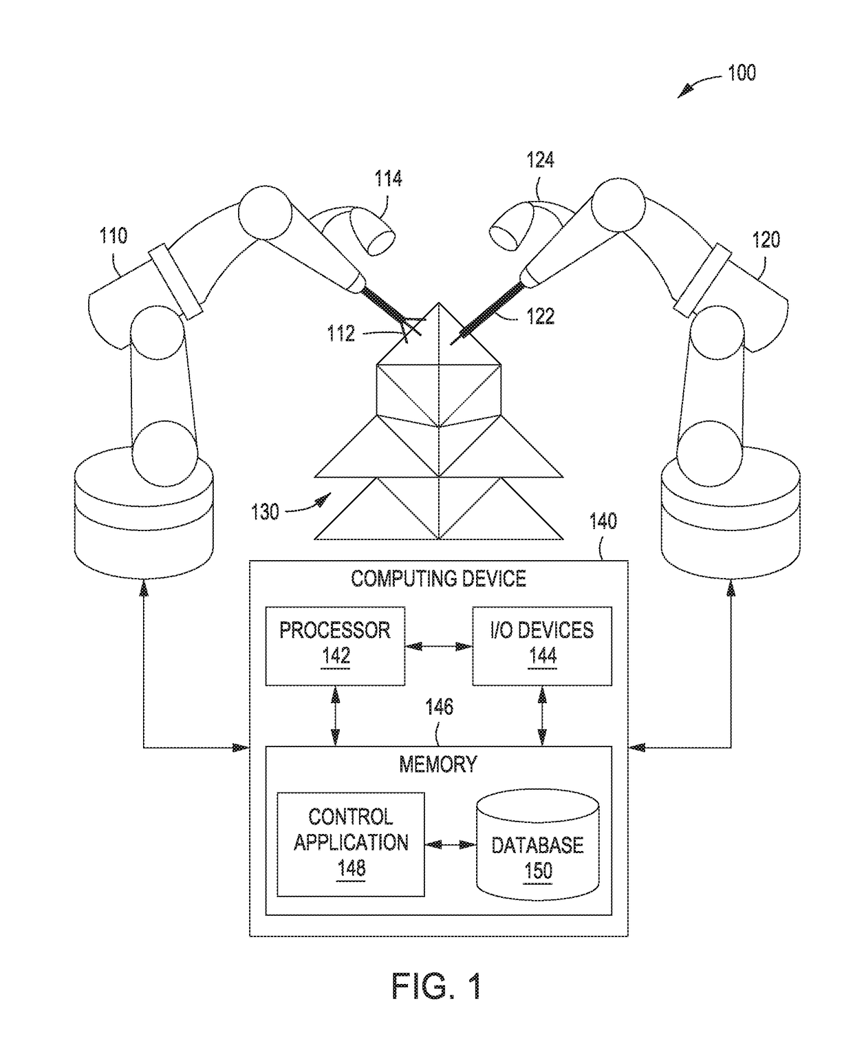
[0016]FIG. 1 illustrates a system configured to implement one or more aspects of the present invention. As shown, a robot system 100 includes a positioning robot 110 and a welding robot 120 configured to cooperatively fabricate a physical mesh 130. Physical mesh may be any technically feasible three-dimensional (3D) structure that includes an assembly of polygons.

[0017]Positioning robot 110 includes a positioning tool 112 and an optical device 114. Positioning tool 112 may be any technically feasible type of manipulator capable of holding, moving, and positioning physical objects. In one embodiment, positioning tool 112 includes a suction device. Via positioning tool 112, positioning ...


PUM

PropertyMeasurementUnit
optical dataaaaaaaaaaa
opticalaaaaaaaaaa
physicalaaaaaaaaaa

Abstract

A robotic assembly cell is configured to generate a physical mesh of physical polygons based on a simulated mesh of simulated triangles. A control application configured to operate the assembly cell selects a simulated polygon in the simulated mesh and then causes a positioning robot in the cell to obtain a physical polygon that is similar to the simulated polygon. The positioning robot positions the polygon on the physical mesh, and a welding robot in the cell then welds the polygon to the mesh. The control application captures data that reflects how the physical polygon is actually positioned on the physical mesh, and then updates the simulated mesh to be geometrically consistent with the physical mesh. In doing so, the control application may execute a multi-objective solver to generate an updated simulated mesh that meets specific design criteria.

Description

BACKGROUND OF THE INVENTIONField of the Invention[0001]Embodiments of the present invention relate generally to robotics and, more specifically, to robotic assembly of a mesh surface.Description of the Related Art[0002]With a conventional computer-aided design (CAD) program, an engineer may generate a 3D model that includes a mesh of interconnected polygons. The engineer may then fabricate a physical object based on the 3D model using a conventional 3D printer. However, one drawback associated with this approach is that conventional 3D printers fabricate physical objects based only on a sliced representation of the 3D model, and not based on the 3D model itself. Consequently, physical objects generated via 3D printing of 3D models are generally inconsistent with the 3D model itself. In addition, conventional 3D printers fabricate objects with low-grade materials, such as plastics. Therefore, conventional 3D printers cannot be used for architectural-scale projects that require high p...

Claims


Application Information

Patent Timeline
Patent Type & Authority Applications(United States)
IPC IPC(8): G06F17/50B25J9/10A01C7/04
CPCG06F17/5018B25J9/1085A01C7/042B25J9/109G05B19/4068B25J9/10B23K9/1037G06F17/5009A01C7/04B25J9/1682B25J9/1687G05B2219/35117G05B2219/37205G05B2219/39132G06F30/23G06F30/20
Inventor ATHERTON, EVAN PATRICKTHOMASSON, DAVIDCONTI, MAURICE UGOKERRICK, HEATHERCOTE, NICHOLAS
Owner AUTODESK INC
Why Eureka
Try Eureka