Cockpit and Crew Rest Air Quality Sensor

a technology for air quality sensors and cockpits, applied in the direction of instruments, energy-efficient board measures, transportation and packaging, etc., can solve the problems of pilot errors or impaired judgment, cognitive degradation of aircraft flight crew, impaired judgment, etc., and achieve the effect of better understanding the risks of crew members

Inactive Publication Date: 2018-12-06
ASTRONICS ADVANCED ELECTRONICS SYST
View PDF6 Cites 8 Cited by
  • Summary
  • Abstract
  • Description
  • Claims
  • Application Information

AI Technical Summary

Benefits of technology

[0006]The present device is a battery powered or energy harvesting sensor that can be placed on any surface, behind a panel, near electronics, near the pilot or crew member. The sensor monitors air quality in real time and real location as needed. In embodiments, the sensor may contain a radio for transmitting the detected air quality to a data collection system. A data collection system may monitor the health of the ambient air around the sensor. The air quality data can be manipulated and sent to a storage and collection system for analysis either during flight or post-flight. Analysts can use this air quality data to better understand crew member risks in specific areas of the aircraft.

Problems solved by technology

Some gasses, such as carbon monoxide can be clear and odorless and may cause cognitive degradation in an aircraft flight crew if present in a high enough concentration.
A pilot may make errors or suffer impaired judgment if carbon monoxide causes sensory degradation.
Such, errors and impaired judgment may lead to catastrophic events.
In a confined area such as a crew rest area, air quality degradation could happen in a matter of minutes causing breathing stress, loss of cognitive skills etc.
Monitoring and event warnings prevent possible aircraft flight safety disturbances, as the events can degrade cognitive ability in the pilot.

Method used


Image

  • Cockpit and Crew Rest Air Quality Sensor
  • Cockpit and Crew Rest Air Quality Sensor
  • Cockpit and Crew Rest Air Quality Sensor

Examples


Embodiment Construction

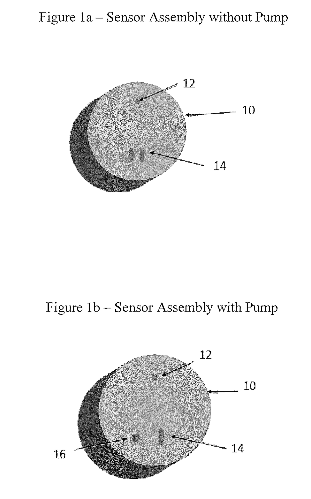
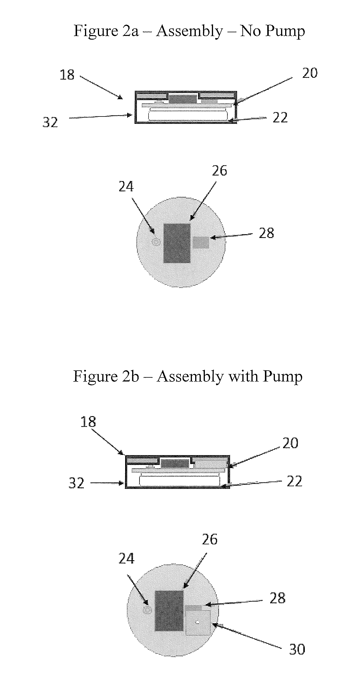
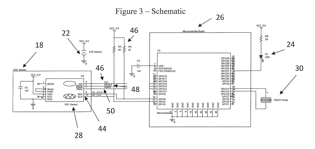
[0014]FIG. 1a depicts a sensor 10 that contains a sensor vent 14 enabling the sensor 10 to access ambient air within a cockpit, crew rest or any other area of an aircraft where sensing air quality is desired. The sensor 10 takes periodic samples of the surrounding air under the control of a microcontroller (uC) 26 (as illustrated in FIG. 2). The sensor 10 and the uC 26 communicate across a bi-directional Inter-Integrated Circuit (I2C) bus 44 (as illustrated in FIG. 3). The uC 26 sends a command string to wake the sensor 10, perform a measurement, then put the senor 10 back to sleep. Placing the sensor 10 in a low power mode conserves power reserves and facilitates powering the sensor 10 from energy harvesting in proper conditions. U.S. patent application Ser. No. 15 / 427,131, by Jouper, titled “Network System for Autonomous Data Collection,” describes powering sensors and communication networks by energy harvesting. The disclosure of U.S. Ser. No. 15 / 427,131 is incorporated by refere...


PUM

PropertyMeasurementUnit
vapor concentrationaaaaaaaaaa
volatile organicaaaaaaaaaa
poweraaaaaaaaaa

Abstract

Disclosed is an area sensor for air quality in the cockpit, crew rest or other area of an aircraft. Noxious fumes, fuel vapors, carbon monoxide and other vapors can cause significant risks to the flight crew of an aircraft. Fumes may cause drowsiness, inattentiveness or confusion to the pilot of an aircraft placing all persons on board an aircraft in danger. There exists a need to monitor and warn the cabin crew of such an event so that measures can be taken, such as donning an oxygen mask, to mitigate the fumes. Many of the vapors encountered that can cause this issue are colorless and/or odorless and therefore not always detected by the flight crew especially if they are in sufficient quantities and exposure is long enough to compromise the pilots cognitive skills.

Description

CROSS-REFERENCE TO RELATED PATENT APPLICATION[0001]This patent application claims a benefit to U.S. Provisional Patent Application Ser. No. 62 / 514,047, titled “Cockpit and Crew Rest Air Quality Sensor,” that was filed on Jun. 2, 2017. The disclosure of U.S. 62 / 514,047 is incorporated by reference herein in its entirety.BACKGROUND OF THE DISCLOSURE[0002]Today, systems for measuring the air quality in an aircraft cabin are tied to an oxygen mask or to the Environmental Cooling System (ECS) that monitors Volatile Organic Compound (VOC) materials in ambient air. The ECS and VOC systems are electrically functional with the host system they are attached to. They control the airflow and warning systems at an aircraft level. Generally, the ECS and VOC systems are at the intake or exhaust of a pump system. All of the air circulated within an aircraft cabin, cockpit and crew rest areas comingle through a single sensor. Because sensors measure comingled air, the sensors take a gross measuremen...

Claims


Application Information

Patent Timeline
Patent Type & Authority Applications(United States)
IPC IPC(8): B64D13/06G01N33/00G08B21/14
CPCB64D2013/0603B64D13/06G01N33/0063G01N33/004G01N33/0047G08B21/14B64D13/00B64D45/00G08B21/12G08B25/10G08B25/14Y02T50/50Y02A50/20
Inventor JOUPER, JEFFREY A.
Owner ASTRONICS ADVANCED ELECTRONICS SYST
Why Eureka
Try Eureka