Two-way lightning protection box with RS485 monitoring data output
A technology of RS485 and monitoring data, which is applied in the direction of emergency protection circuit devices, circuit devices, emergency protection circuit devices, etc. used to limit overcurrent/overvoltage, and can solve problems such as intrusion of lightning electromagnetic pulses, infringement, and influence on power distribution systems , to achieve the effect of reducing user costs, complete functions, and increasing danger
- Summary
- Abstract
- Description
- Claims
- Application Information
AI Technical Summary
Problems solved by technology
Method used
Image
Examples
Embodiment 1
[0058] Embodiment 1: the concrete structure of the present invention is as follows:
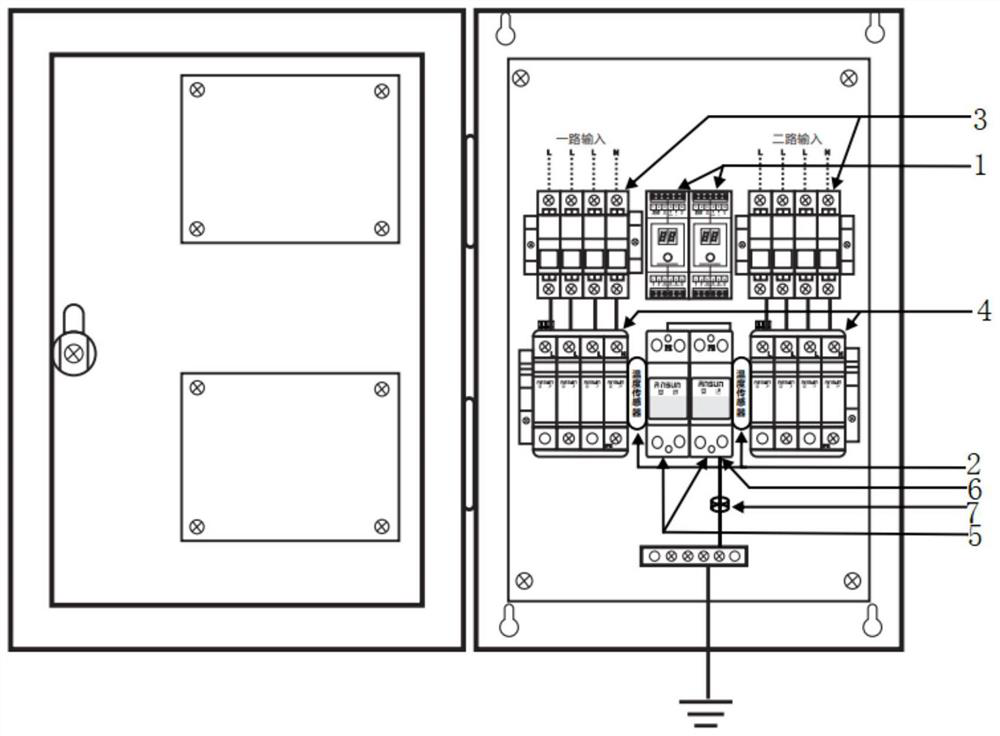
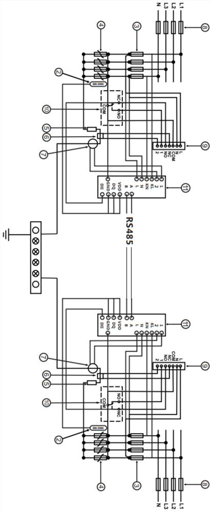
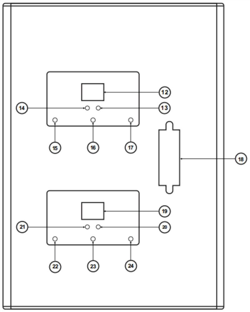
[0059] Please refer to the attached Figure 1-10 , a dual-way lightning protection box with RS485 monitoring data output of the present invention includes a box body, and also includes:
[0060] Two sets of intelligent lightning protection monitoring modules 1 with a parallel circuit structure, each intelligent lightning protection monitoring module 1 is used to collect data and alarm information. It has two communication interfaces, and two sets of parallel intelligent lightning protection monitoring modules 1 constitute a dual-loop monitoring system ;
[0061] The lightning protector 4 has a remote signaling port 10, which includes a first on-site monitoring circuit and a first remote monitoring circuit that are electrically connected to the dual-loop monitoring system;
[0062] The temperature sensor 2 is close to the side of the lightning protection device 4, and it is used to sense the...
Embodiment 2
[0087] Such as Figure 5-7 as shown, Figure 5 It is a partial I circuit diagram of the intelligent lightning protection monitoring module of the present invention. Image 6 It is a partial II circuit diagram of the intelligent lightning protection monitoring module of the present invention. Figure 7 For the partial III circuit diagram of the intelligent lightning protection monitoring module of the present invention, the Figure 5-7 The same letters in A-J are connected to form an overall circuit diagram.
[0088] The intelligent lightning protection monitoring circuit of the present invention comprises:
[0089] Single-chip microcomputer U10, controlling the operation of the lightning protection monitor;
[0090] The communication transceiver U9 is connected to the single-chip microcomputer U10 and establishes a communication transmission channel with the single-chip microcomputer U10;
[0091] The logic chip U11 is connected with the LED2 lamp group and controls the wor...
Embodiment 3
[0153] The following is the monitoring and indicating circuit principle of the intelligent lightning protection monitor:
[0154] Such as Figure 8-10 as shown, Figure 8 It is a partial I circuit diagram of the 1# and 2# loop monitoring systems in the double-loop lightning protection box of the present invention. Figure 9 It is a partial II circuit diagram of the 1# and 2# loop monitoring systems in the double-loop lightning protection box of the present invention. Figure 10 It is a partial III circuit diagram of the 1# and 2# loop monitoring systems in the double-loop lightning protection box of the present invention. Will Figure 8-10 A1-A10 in A1-A10 are connected by the same letter number to form an overall circuit diagram.
[0155] The monitoring indication circuit of the present invention is set in the monitor, which includes a first logic chip U1, a second logic chip U2, a first digital tube, a second digital tube, a resistor R1, a resistor R2, a diode D1, a diod...
PUM
 Abstract
Description
Claims
Application Information
 - R&D
- Intellectual Property
- Life Sciences
- Materials
- Tech Scout
- Unparalleled Data Quality
- Higher Quality Content
- 60% Fewer Hallucinations
Browse by: Latest US Patents, China's latest patents, Technical Efficacy Thesaurus, Application Domain, Technology Topic, Popular Technical Reports.
© 2025 PatSnap. All rights reserved.Legal|Privacy policy|Modern Slavery Act Transparency Statement|Sitemap|About US| Contact US: help@patsnap.com


