Automatic driving system

a driving system and automatic technology, applied in the direction of vehicle position/course/altitude control, process and machine control, instruments, etc., can solve the problems of inability to realize the control of a vehicle based on a predetermined traveling plan, inability to study abnormalities satisfactorily, and interruption of the flow of control

a driving system and automatic technology, applied in the direction of vehicle position/course/altitude control, process and machine control, instruments, etc., can solve the problems of inability to realize the control of a vehicle based on a predetermined traveling plan, inability to study abnormalities satisfactorily, and interruption of the flow of control

US20180348769A1Active Publication Date: 2018-12-06TOYOTA JIDOSHA KK

Image

  • Automatic driving system
  • Automatic driving system
  • Automatic driving system

Examples


first embodiment

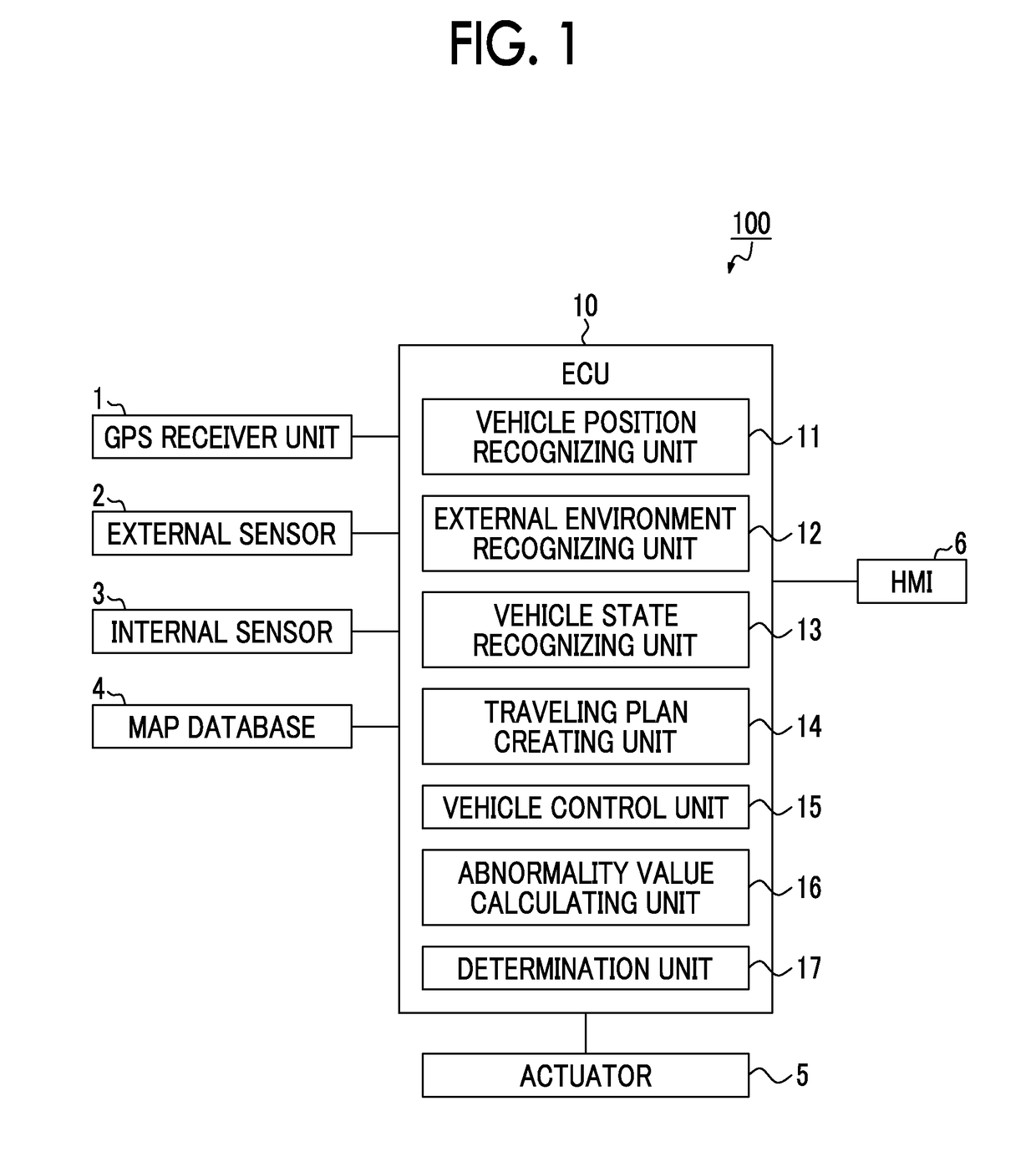
[0029]FIG. 1 is a block diagram illustrating an automatic driving system according to a first embodiment. An automatic driving system 100 illustrated in FIG. 1 is mounted in a vehicle such as an automobile and performs automatic driving control of the vehicle. Automatic driving control is vehicle control of causing a vehicle to travel automatically to a preset destination. In automatic driving control, an occupant does not need to perform a driving operation and the vehicle travels automatically.

[0030]

[0031]As illustrated in FIG. 1, the automatic driving system 100 includes an electronic control unit (ECU) 10 that comprehensively controls the system. The ECU 10 is an electronic control unit including a central processing unit (CPU), a read only memory (ROM), a random access memory (RAM), and a controller area network (CAN) communication circuit. The ECU 10 embodies various functions, for example, by loading a program stored in the ROM into the RAM and causing the CPU to execute the ...

second embodiment

[0102]FIG. 5 is a block diagram illustrating an automatic driving system according to a second embodiment. An automatic driving system 200 according to the second embodiment illustrated in FIG. 5 is the same as that in the first embodiment, except that a command value is calculated based on a composite target value of a control target value and a stabilization target value which are mixed according to the abnormality value. The elements equal or corresponding to those in the first embodiment will be referenced by the same reference signs and description thereof will not be repeated.

[0103]

[0104]As illustrated in FIG. 5, the automatic driving system 200 according to the second embodiment includes a stabilization target value calculating unit 21 in an ECU 20. The stabilization target value calculating unit 21 calculates a stabilization target value which is a control target value for stabilizing behavior of the vehicle. The stabilization target value calculating unit 21 calculates the ...


PUM


Abstract

An automatic driving system includes an electronic control unit. The electronic control unit is configured to create a traveling plan including a control target value of automatic driving control of a vehicle based on a position of the vehicle of a map, a vehicle state, and an external environment, to calculate an abnormality value, to determine, based on the abnormality value, whether the vehicle is an a normal state, an abnormal state, or an intermediate state, and to create an abnormal traveling plan as the traveling plan when it has been determined that the vehicle is in the abnormal state.

Description

INCORPORATION BY REFERENCE[0001]The disclosure of Japanese Patent Application No. 2017-110394 filed on Jun. 2, 2017 including the specification, drawings and abstract is incorporated herein by reference in its entirety.BACKGROUND1. Technical Field[0002]The disclosure relates to an automatic driving system.2. Description of Related Art[0003]PCT International Publication No. 2007 / 141063 is known as technical literature for a controller of a vehicle. In this publication, a method of adjusting two or more controllers for vehicle behavior that operate in parallel is described, in which the stability of each controller is evaluated in a first step, the stability of a group of controllers is evaluated in a second step, and the stability evaluation results of the controllers and the stability evaluation result of the group of controllers are compared in a third step. In this method, when a separation between the stability evaluation results of the controllers and the stability evaluation re...

Claims


Application Information

Patent Timeline
06 Dec 2018
Publication
US20180348769A1
IPC
G05D1/02
CPC
G05D1/0214; G05D1/0274; G05D1/0088; G05D2201/0213; G05D1/0223; G05D1/0251; G05D1/0257; G05D1/0276
Inventors
SATO, KUNIHITO; KAMATA, NOBUHIDE