
Home Automation System

a home automation and system technology, applied in the field of home automation systems, can solve the problems of inability to definitively detect users, complicated installation, and complex technical aspects, and achieve the effect of simplifying installation and use of home automation systems and improving user position detection

Inactive Publication Date: 2018-12-06
INNOGY SE
View PDF26 Cites 11 Cited by
  • Summary
  • Abstract
  • Description
  • Claims
  • Application Information

AI Technical Summary

Benefits of technology

The patent is about improving the accuracy of position detection in home automation systems by using existing technologies. This is achieved by providing additional position signs, such as by converting current signatures of transmitters in real-time based on their known position. The position detection is further improved by an iterative adaption or expansion of the position signs for different local regions. The evaluation of the signs can be carried out by using a neuronal network that learns the user's positions and makes corrections based on user feedback. Additionally, the patent proposes a solution to prevent the transmitter from consuming its energy too quickly by sending its transmitter identification in specified intervals. This increases the service life of the transmitter.

Problems solved by technology

However, these infrared sensors only respond to movements such that the user cannot be definitively detected when they do not move much.
Other methods, such as for example ultrasonic sensors or microwave sensors have not caught on in the mass market because they require a plurality of sensors, they are technically complex and are thus complicated to install.

Method used


Image

  • Home Automation System
  • Home Automation System
  • Home Automation System

Examples


Embodiment Construction

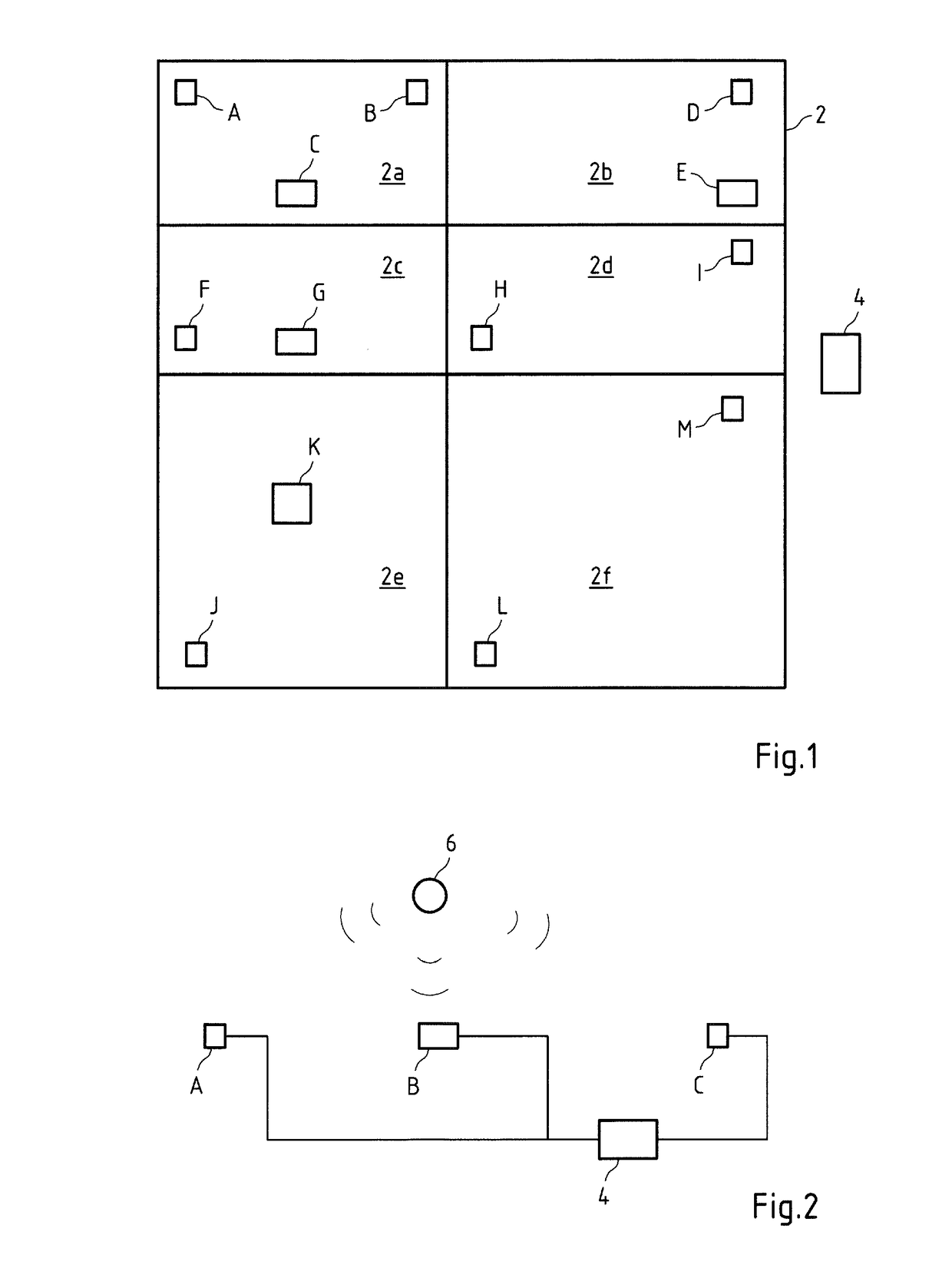
[0072]FIG. 1 shows a region 2 in which a home automation system is established. The region 2 is divided into six spatial regions 3a-f. The spatial regions 2a-f can for example be different rooms in a building or also determined regions within a room. At least one of the sensors A-M of the home automation system is installed in each of the spatial regions 2a-f.

[0073]In the example shown in FIG. 1, the sensors A, B and C are for example installed in the region 2a, the sensors D and E are installed in the region 2b, the sensors F and G are installed in the region 2c, the sensors H and I are installed in the region 2d, the sensors J and K are installed in the region 2e and the sensors L and M are installed in the region 2f.

[0074]In addition to the sensors A-M, an evaluation device 4 is provided which is in wireless or wired communication with the sensors A-M.

[0075]The sensors A-M can be the most varied of sensors or actuators of a home automation system. Conceivable sensors A to M in ...


PUM


Abstract

Provided herein are embodiments of a home automation system. The home automation system includes display means configured to display a view of at least one part of a floor plan of a spatial environment of the home automation system. An intuitive and simplified set-up takes place by the programming means being configured to program at least one action of an actuator of the home automation system based on the currently displayed view of the floor plan and a function of the actuator and / or a sensor of the home automation system.

Description

CROSS-REFERENCE TO RELATED PATENT APPLICATIONS[0001]This patent application is a continuation of PCT Application No. PCT / EP2016 / 075761, filed Oct. 26, 2016, which claims priority to German Application No. 10 2016 102 402.3, filed Feb. 11, 2016, the entire teachings and disclosure of which are incorporated herein by reference thereto.FIELD[0002]The subject matter relates to a home automation system and a method for operating a home automation system.BACKGROUND[0003]Home automation solutions are becoming increasingly interesting for private users. The components used in home automation have been known for a long time such that comfortable operating concepts come in the focus to when developing home automation solutions. It is in particular becoming increasingly more important to precisely and reliably detect the position or presence of a user in the home controlled by the home automation system. Exact position detection allows new operating concepts to be implemented. New, intuitive o...

Claims


Application Information

Patent Timeline
IPC IPC(8): H04L12/28G06T7/73
CPCH04L12/282H04L12/2827G06T7/74G06T2207/30196G05B15/02
Inventor BECKER, GERNOT
Owner INNOGY SE
Learn More