
Oil Field Services Apparatus and Methods

a technology for oil field services and equipment, applied in the direction of survey, hoisting equipment, cables, etc., can solve the problems of reducing the service life of the tool, increasing the length of the tool, and increasing the quantity of electrical power used to drive or otherwise energize the various internal components of the tool,

Inactive Publication Date: 2018-12-13
SCHLUMBERGER TECH CORP
View PDF5 Cites 16 Cited by
  • Summary
  • Abstract
  • Description
  • Claims
  • Application Information

AI Technical Summary

Benefits of technology

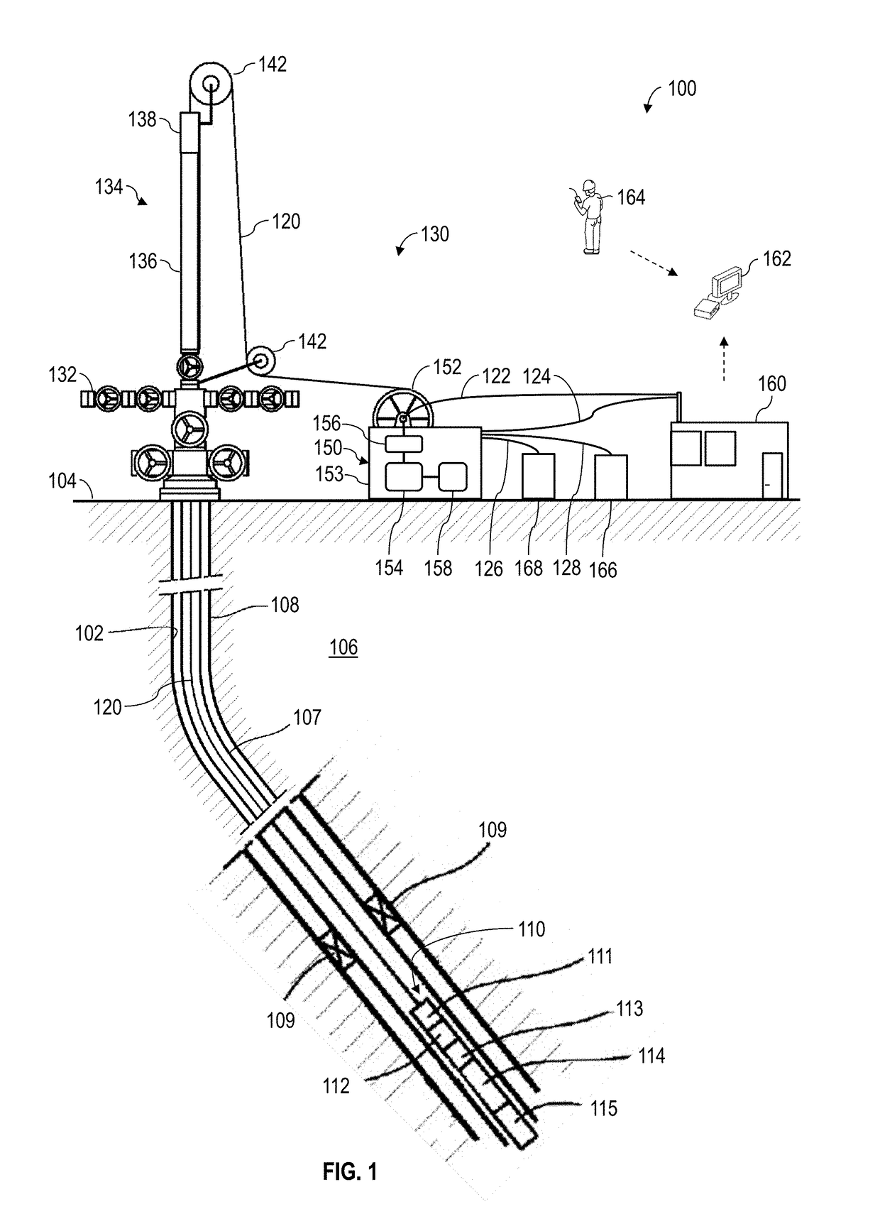
The patent text discusses the problem of downhole tools becoming longer and heavier as they perform more functions, causing excessive strains on the lines used to convey them. The text describes an apparatus that can be used to deploy and convey downhole tools while reducing the strains on the lines. The apparatus includes a line, a reel for storing the line, an apparatus for conveying the line into and out of the wellbore, and surface well control apparatus at a wellhead. The technical effect of the apparatus is to allow for longer and more complex downhole tools to be used without causing excessive wear and tear on the lines, which can limit their operational life.

Problems solved by technology

In working with deeper and more complex wellbores, it becomes more likely that downhole tools, tool strings, and / or other downhole apparatus may include numerous testing, navigation, and / or communication tools, resulting in increasingly longer tools that consume increasingly larger quantities of electrical power to drive or otherwise energize various internal components of such tools.
As more and more sophisticated functions are performed downhole, downhole tools have grown in weight to a point where downhole deployment and conveyance operations impart excessive stresses and strains to the lines, resulting in excessive wear and tear and, thus, diminished operational life.

Method used


Image

  • Oil Field Services Apparatus and Methods
  • Oil Field Services Apparatus and Methods
  • Oil Field Services Apparatus and Methods

Examples


Embodiment Construction

[0028]It is to be understood that the following disclosure provides many different embodiments, or examples, for implementing different features of various embodiments. Specific examples of components and arrangements are described below to simplify the present disclosure. These are, of course, merely examples and are not intended to be limiting. In addition, the present disclosure may repeat reference numerals and / or letters in the various examples. This repetition is for simplicity and clarity, and does not in itself dictate a relationship between the various embodiments and / or configurations discussed. Moreover, the formation of a first feature over or on a second feature in the description that follows may include embodiments in which the first and second features are formed in direct contact, and may also include embodiments in which additional features may be formed interposing the first and second features, such that the first and second features may not be in direct contact....


PUM


Abstract

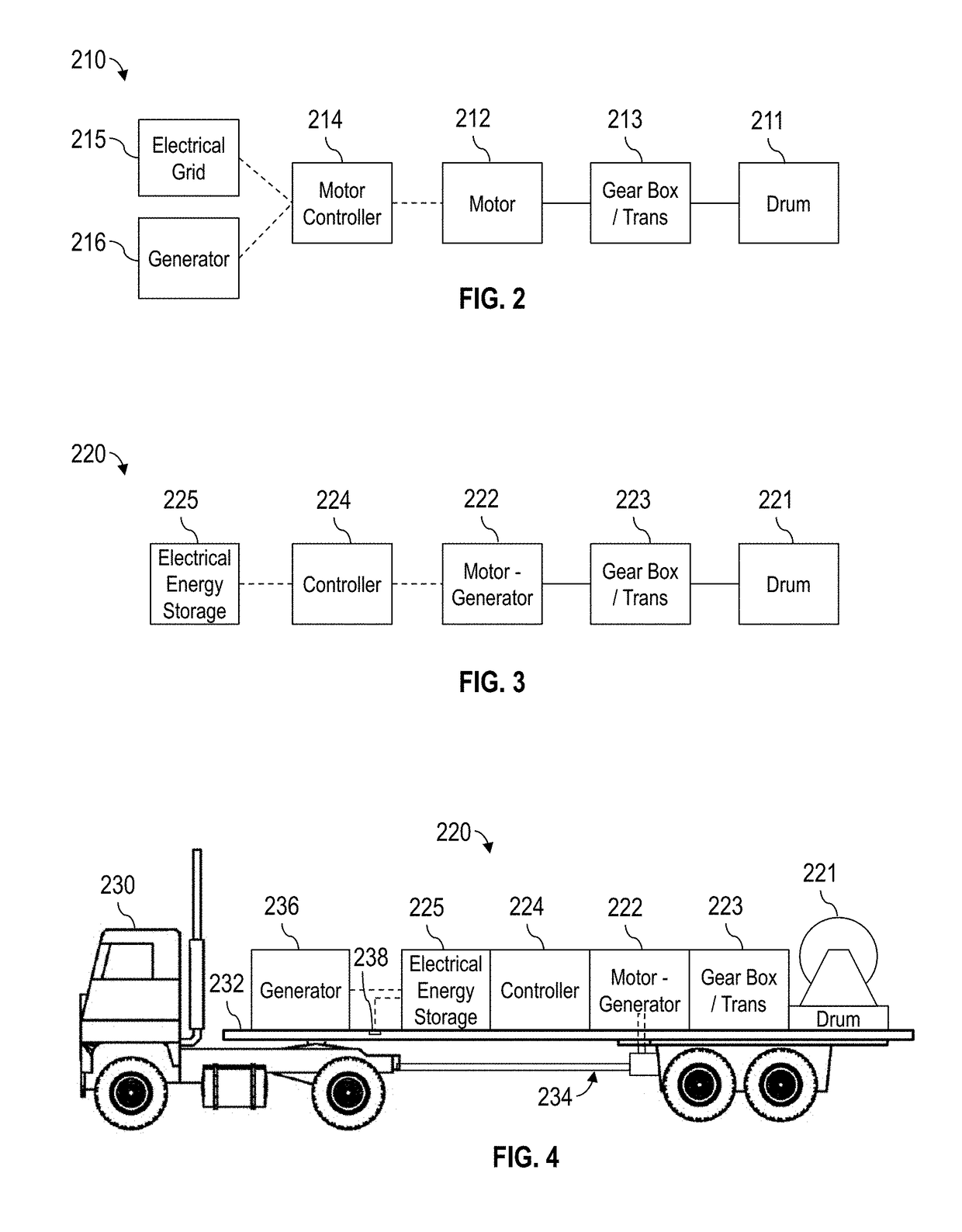
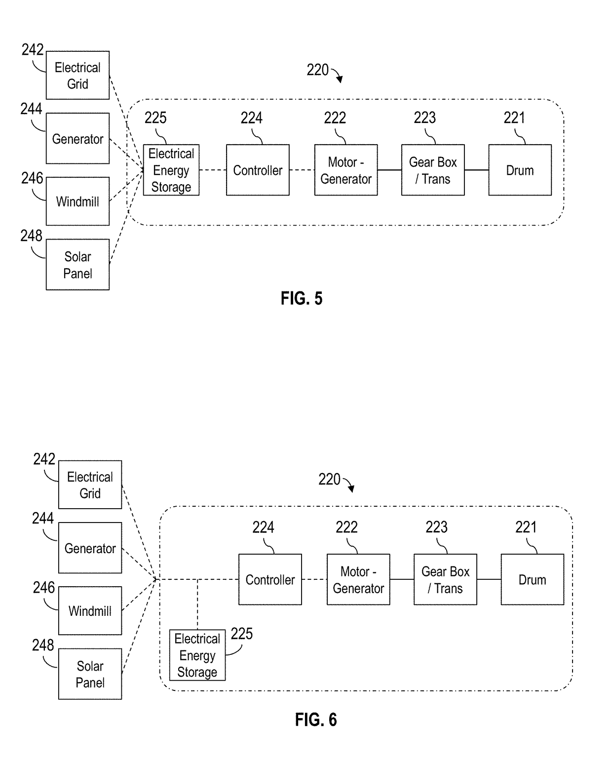
Oil field services apparatus and method. The apparatus comprises a conveyance system operable for lowering and retrieving a downhole tool in and out of a wellbore. The conveyance system comprises a drum operable for rotating and receiving a line connectable with the downhole tool, a motor-generator mechanically connected with the drum, and an energy storage electrically connected with the motor-generator. The motor-generator may be operable for receiving electrical energy to impart torque to the drum and receiving torque from the drum to generate electrical energy. The energy storage may be operable for storing electrical energy received from the motor-generator.

Description

BACKGROUND OF THE DISCLOSURE[0001]Wells are generally drilled into a land surface or ocean bed to recover natural deposits of oil and gas, as well as other natural resources that are trapped in geological formations in the Earth's crust. Wellbores may be drilled along a trajectory to reach one or more subterranean rock formations containing such natural resources. Information about the subterranean formations and formation fluid, such as measurements of the formation pressure, formation permeability, and recovery of formation fluid samples, may be utilized to increase well production and to predict the economic value, the production capacity, and the production lifetime of the subterranean formation.[0002]Various well deployment wires or cables (e.g., slicklines, wirelines, multilines, and the like), collectively referred to hereinafter as lines, may be utilized to convey downhole tools to reach the oil and gas deposits and to perform various well treatment and / or well intervention ...

Claims


Application Information

Patent Timeline
IPC IPC(8): E21B19/00E21B19/084E21B17/00H02G11/02H01B7/00H01B7/02G02B6/44B66D1/12
CPCE21B19/008E21B19/084E21B17/003H02G11/02H01B7/0009H01B7/0275G02B6/4413G02B6/4415B66D1/12E21B47/12E21B19/22G02B6/50E21B47/135
Inventor PESSIN, JEAN-LOUISGEORGET, STEPHANEBOUFFE, MAXIMECORRE, PIERRE-YVES
Owner SCHLUMBERGER TECH CORP
Learn More