Silencer and ejector in which silencer is used

a technology of silencer and ejector, which is applied in the field of silencer, can solve the problems of difficult port closure from the exterior, deterioration of vacuum pressure and suction flow rate when discharge port is closed, etc., and achieve the effects of remarkable silencing effect, reduced discharge pressure, and reduced discharge nois

Active Publication Date: 2018-12-13
SMC CORP
View PDF0 Cites 2 Cited by
  • Summary
  • Abstract
  • Description
  • Claims
  • Application Information

AI Technical Summary

Benefits of technology

[0015]In accordance with the ejector of the present invention, the installation location of the ejector to which the silencer is attached is not restricted, discharge from the discharge port is carried out without any impediment, and discharge noise is reduced. More specifically, even in the case that the ejector to which the silencer is attached is installed in any arbitrary orientation, discharge gas can be discharged from the plurality of discharge ports in directions perpendicular to the axial direction of the tubular portion, while in addition, the silencer can be installed without separating the ejector a certain distance away from a wall surface or the like. Further, since the plurality of discharge ports are provided in the silencer, unlike the case in which a discharge port is provided at only one location, there is an advantage in that it is difficult for the ports to be closed from the exterior. Furthermore, since the plurality of discharge ports are dispersed and act to discharge the pressure fluid, the discharge pressure can be reduced, and the silencing effect is remarkable.
[0016]According to the present invention, it is possible to provide a silencer and an ejector using a silencer, in which the installation location of the fluid pressure device to which the silencer is attached is not restricted, discharge from the discharge port is carried out without any impediment, and discharge noise is reduced.

Problems solved by technology

Further, since the discharge port is provided in only one location, for example, in the case that the silencer is attached to the ejector, there is a problem in that performance of the suction flow rate and the vacuum pressure deteriorates when the discharge port is closed.
Further, since the plurality of discharge ports are provided in the silencer, unlike the case in which a discharge port is provided at only one location, there is an advantage in that it is difficult for the ports to be closed from the exterior.

Method used


Image

  • Silencer and ejector in which silencer is used
  • Silencer and ejector in which silencer is used
  • Silencer and ejector in which silencer is used

Examples


Embodiment Construction

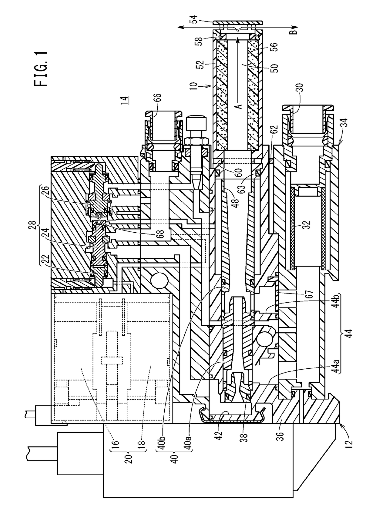
[0026]Preferred embodiments of a silencer according to the present invention in relation to an ejector in which the silencer is incorporated will be described in detail below with reference to the accompanying drawings.

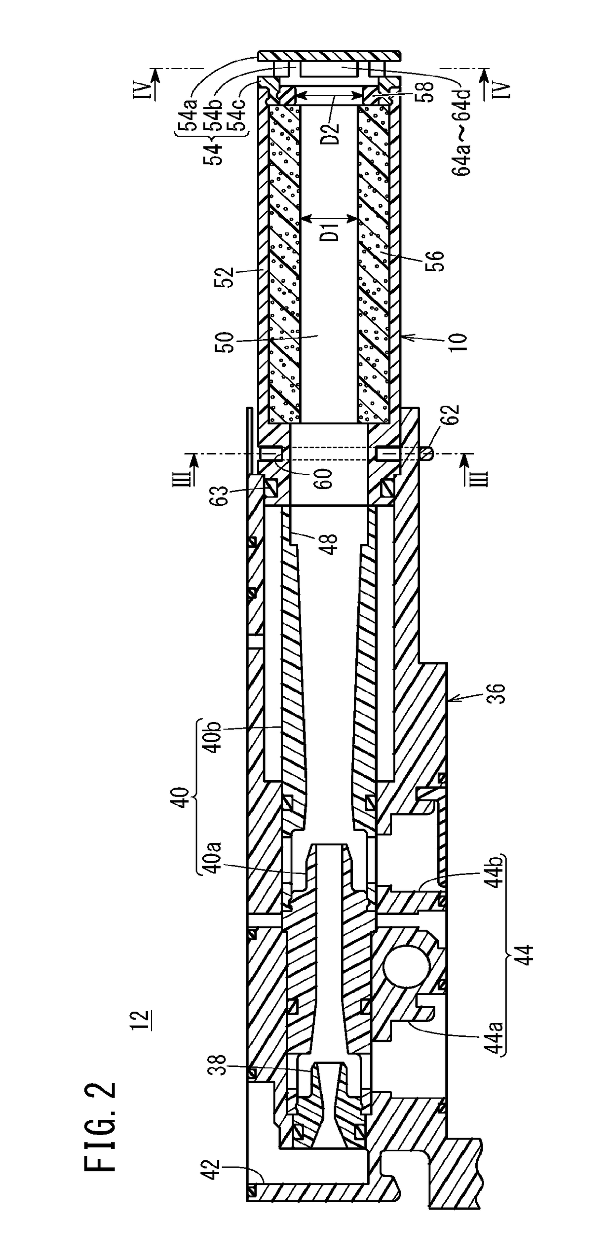
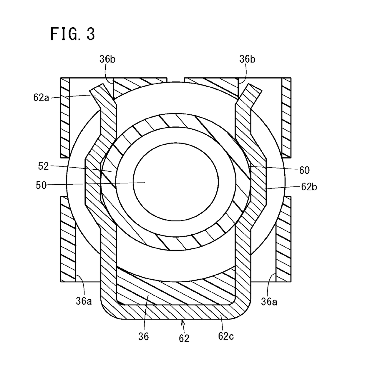
[0027]FIG. 1 is a cross-sectional view showing a vacuum generating unit 14 including an ejector 12 to which a silencer 10 according to a first embodiment is attached, FIG. 2 is a cross-sectional view showing the ejector 12 illustrated in FIG. 1, FIG. 3 is a cross-sectional view taken along line of the silencer 10 and the ejector 12 shown in FIG. 2, and FIG. 4 is a cross-sectional view taken along line IV-IV of the silencer 10 shown in FIG. 2. As shown in FIG. 1, the vacuum generating unit 14 is constituted from the ejector 12 which functions as a vacuum generating mechanism, a solenoid valve unit 20 having a vacuum breaking pilot valve 16 and a vacuum supplying pilot valve 18, a switching valve unit 28, and a filter unit 34 adapted to remove dust and the like containe...


PUM


Abstract

A silencer is equipped with a hollow tubular portion in which a discharge flow passage is formed that communicates on one end side thereof with a discharge port of a fluid pressure device (ejector) through which a pressure fluid is discharged, a cap member attached to another end part of the tubular portion, a sound absorbing member attached to an inner wall surface of the tubular portion, and a plurality of discharge ports adapted to discharge the pressure fluid, which has passed through the discharge flow passage in an axial direction of the tubular portion, in radial directions perpendicular to the axial direction.

Description

CROSS-REFERENCE TO RELATED APPLICATION[0001]This application is based upon and claims the benefit of priority from Japanese Patent Application No. 2017-114261 filed on Jun. 9, 2017, the contents of which are incorporated herein by reference.BACKGROUND OF THE INVENTIONField of the Invention[0002]The present invention relates to a silencer adapted to reduce discharge noise of a pressure fluid that is discharged from a fluid pressure device, as well as to an ejector in which such a silencer is used.Description of the Related Art[0003]Conventionally, discharge noise of a pressure fluid (compressed air) that is discharged from a fluid pressure device such as an ejector is large, and therefore, by installing a silencer on the side of a discharge port of the fluid pressure device, lessening of the discharge noise can be achieved (See Japanese Laid-Open Patent Publication No. 2012-218099). This type of silencer is equipped with a hollow tubular portion in which a discharge flow passage is f...

Claims


Application Information

Patent Timeline
Patent Type & Authority Applications(United States)
IPC IPC(8): F01N1/10F01N1/08
CPCF01N1/10F01N1/085B65H2601/324G10K11/161F04B39/005F04B39/0055F04B39/0083F04F5/20F04F5/44G10K11/16B65G47/91G10K2210/3214G10K2210/3224F04C29/063
Inventor NAKAYAMA, TORUSUGANO, KOJIENOMOTO, MASAYUKIYAMAMOTO, MASAYOSHI
Owner SMC CORP
Why Eureka
Try Eureka