Flow Passage Control Valve for Muffler

a flow passage control valve and muffler technology, applied in the field of vehicle mufflers, can solve the problems of increased cost of materials, difficult to accurately control the gas channel, and difficulty in improving engine power, so as to achieve effective improvement of engine power, reduce exhaust gas discharge noise, and reduce exhaust noise

Inactive Publication Date: 2010-06-10
HYUNDAI MOTOR CO LTD
View PDF19 Cites 12 Cited by
  • Summary
  • Abstract
  • Description
  • Claims
  • Application Information

AI Technical Summary

Benefits of technology

[0028]According to various aspect of the flow passage control valve of the present invention, since the cross-sectional area of the exhaust gas channel and the open amount of the valve are small when the engine is driven at a low speed, in which the influence of booming noise is large, the exhaust gas discharge noise is reduced and exhaust noise is effectively reduced. Further, when the engine is driven at a middle speed or a high speed, the cross-sectional area of the exhaust gas channel and the open amount of the valve increase in proportion to the driving speed of the engine and the engine power is effectively improved, such that it is possible to reduce the cost of materials because it is not required to mount a spring having large strength to support the valve, and accurately control the exhaust gas channel because less pulsation pressure of the exhaust gas is applied.

Problems solved by technology

When a spring type flow passage control vale having the above configuration in the related art is used, since the valve body is supported by the spring, the exhaust gas channel formed through the first baffle is opened in linear proportion to the exhaust gas pressure exerted in the valve body, in which the exhaust gas channel should be more opened to improve the engine power; however, the amount of opening of the variable valve is limited by the support force of the spring, which linearly increases, such that it is difficult to improve the engine power.
Accordingly, it is difficult to accurately control the gas channel and it is required to use a special steel spring having high strength because the support spring that supports the valve body is exposed to the high-temperature exhaust gas, such that the cost of materials increases.

Method used


Image

  • Flow Passage Control Valve for Muffler
  • Flow Passage Control Valve for Muffler
  • Flow Passage Control Valve for Muffler

Examples


Embodiment Construction

[0037]Reference will now be made in detail to various embodiments of the present invention(s), examples of which are illustrated in the accompanying drawings and described below. While the invention(s) will be described in conjunction with exemplary embodiments, it will be understood that present description is not intended to limit the invention(s) to those exemplary embodiments. On the contrary, the invention(s) is / are intended to cover not only the exemplary embodiments, but also various alternatives, modifications, equivalents and other embodiments, which may be included within the spirit and scope of the invention as defined by the appended claims.

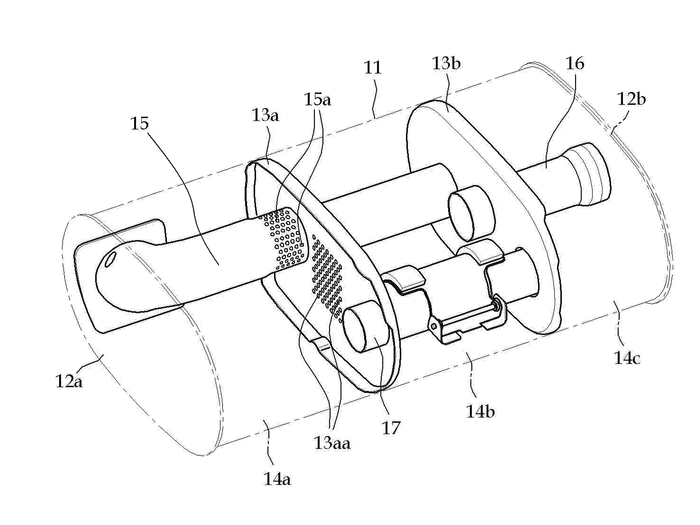
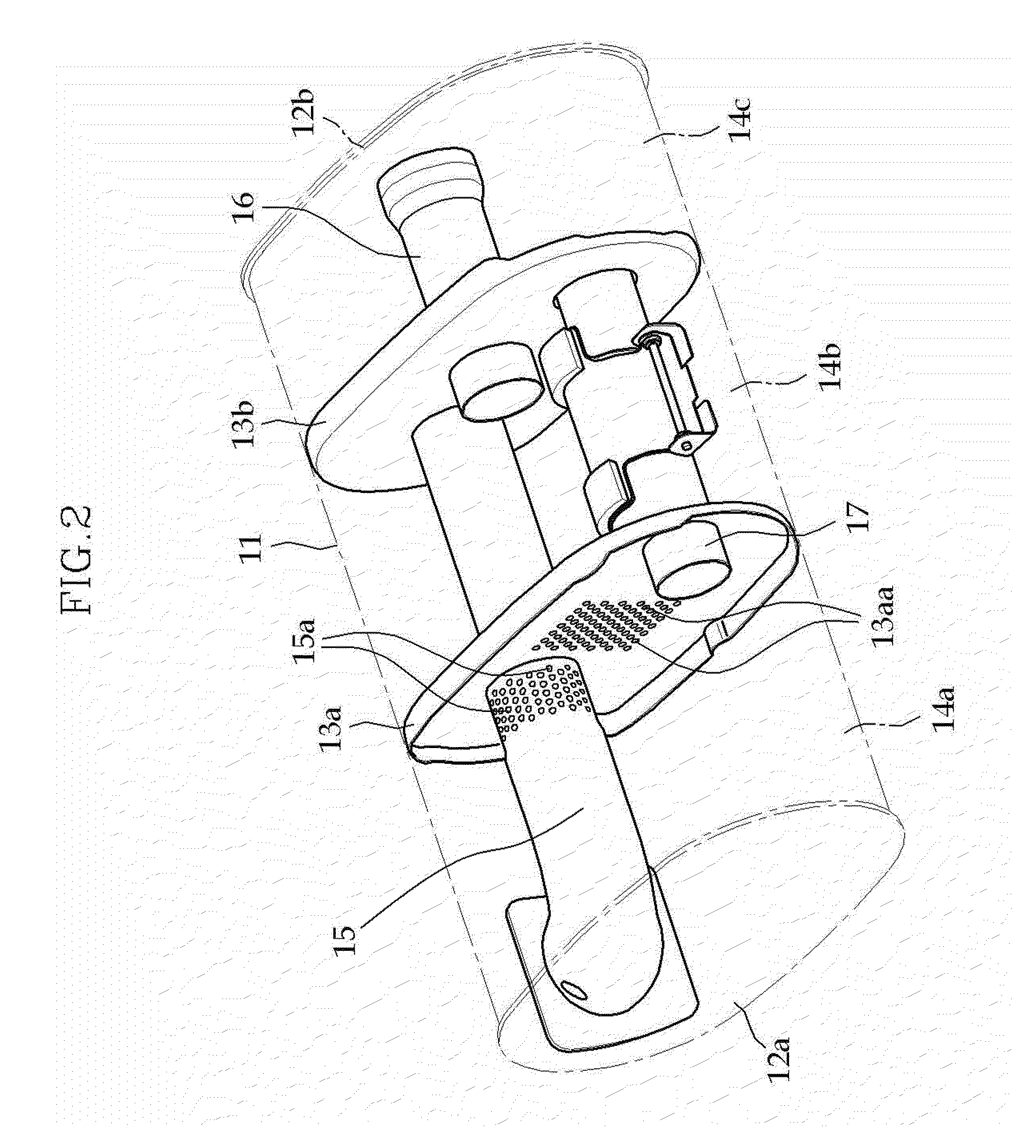
[0038]Referring to FIG. 2, the openings of both sides of a muffler housing 11 having a substantially elliptical box shape are covered by a front cap 12a and a rear cap 12b to seal the inside of the muffler housing 11. Two baffles 13a, 13b are disposed to be individually integrally fixed at a predetermined distance in the longitudinal ...


PUM


Abstract

A flow passage control valve for a muffler may include an opening formed through a guide pipe, which forms an exhaust gas channel in the muffler, to form another exhaust gas channel, and a valve body adjusts an open amount of the opening by using a difference between an exhaust gas pressure exerted through the opening and a weight of the valve body.

Description

CROSS-REFERENCE TO RELATED APPLICATIONS[0001]The present application claims priority to Korean Application Serial Number 10-2008-0122517, filed on Dec. 4, 2008, the entire contents of which is incorporated herein for all purposes by this reference.BACKGROUND OF THE INVENTION[0002]1. Field of the Invention[0003]The present invention relates to a muffler of a vehicle, particularly a flow passage control valve for a muffler that uses the gravity to change an exhaust gas flow passage inside the muffler.[0004]2. Description of Related Art[0005]Mufflers of vehicles in the related art have structures including a plurality of chambers that is formed by disposing one or more baffles in a muffler housing sealed to have a predetermined volume, an exhaust gas intake pipe that allows exhaust gas to flow inside the muffler housing, and an exhaust gas discharge pipe that allows the exhaust gas to flow outside from the muffler housing such that the exhaust gas that has flowed in the muffler housing...

Claims


Application Information

Patent Timeline
Patent Type & Authority Applications(United States)
IPC IPC(8): F01N1/00
CPCF01N1/084F01N1/089F16K17/12F01N2290/10F01N2490/06F01N1/166F01N1/02F01N1/16F01N13/08
Inventor HAN, HAKSON
Owner HYUNDAI MOTOR CO LTD
Why Eureka
Try Eureka