Y splitter for exhaust systems

a splitter and exhaust system technology, applied in the direction of branching pipes, machines/engines, transportation and packaging, etc., can solve the problems of complicated ground clearance problems, high back pressure buildup, and difficult to reach the ground, so as to reduce back pressure buildup, improve ground clearance, and reduce exhaust pressure peaks

Inactive Publication Date: 2012-05-22
BUTLER BOYD L
View PDF12 Cites 11 Cited by
  • Summary
  • Abstract
  • Description
  • Claims
  • Application Information

AI Technical Summary

Benefits of technology

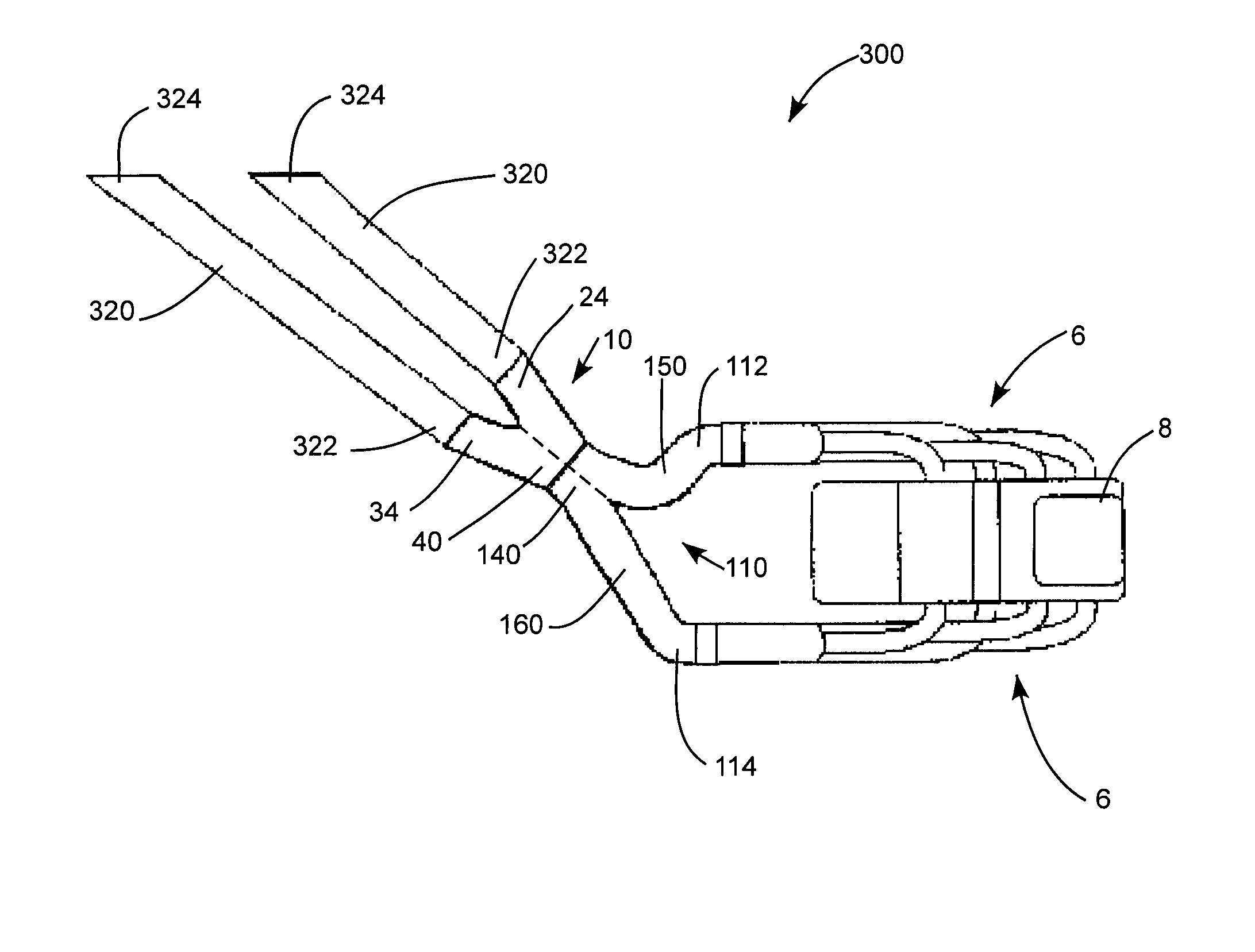
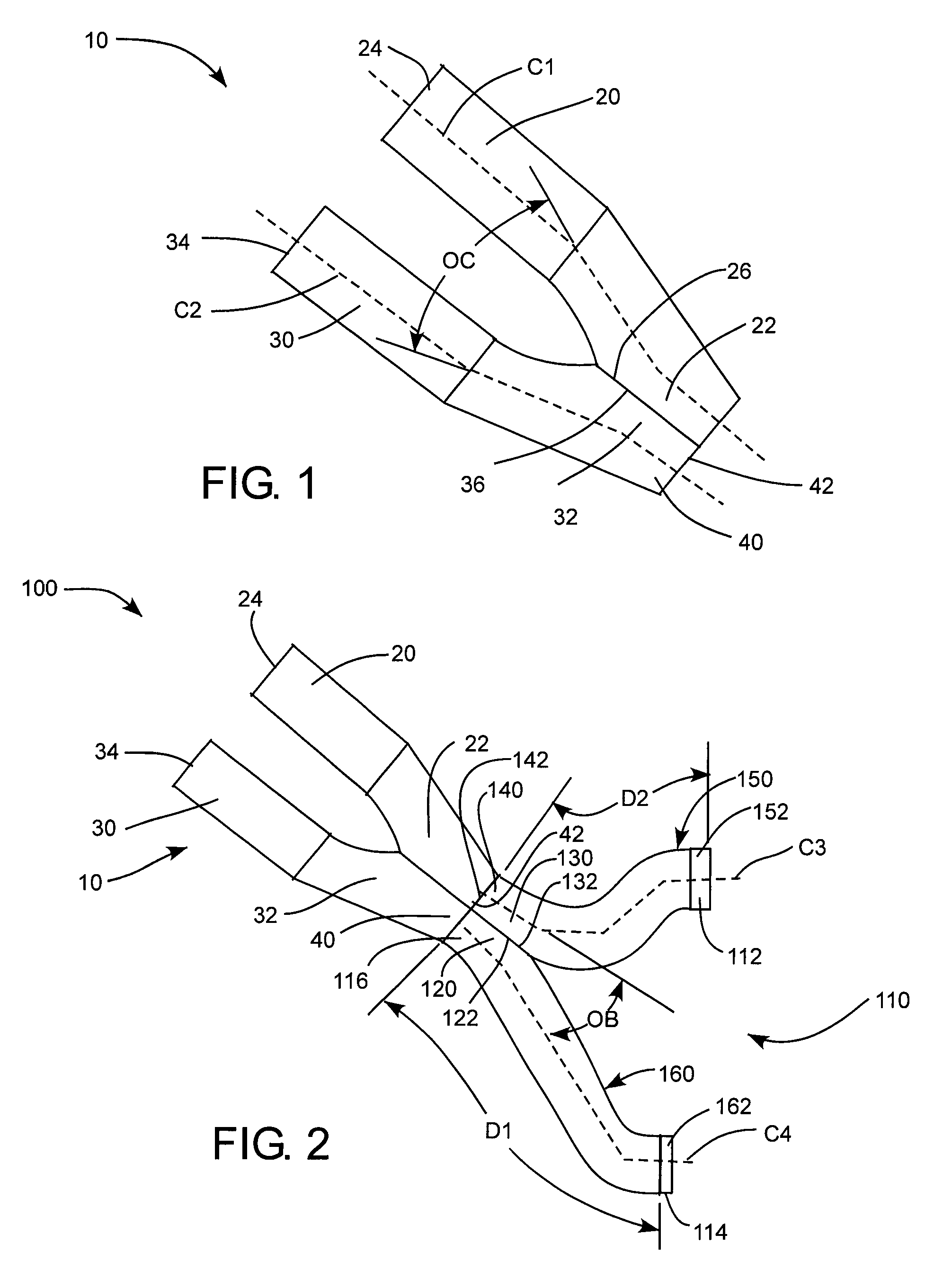
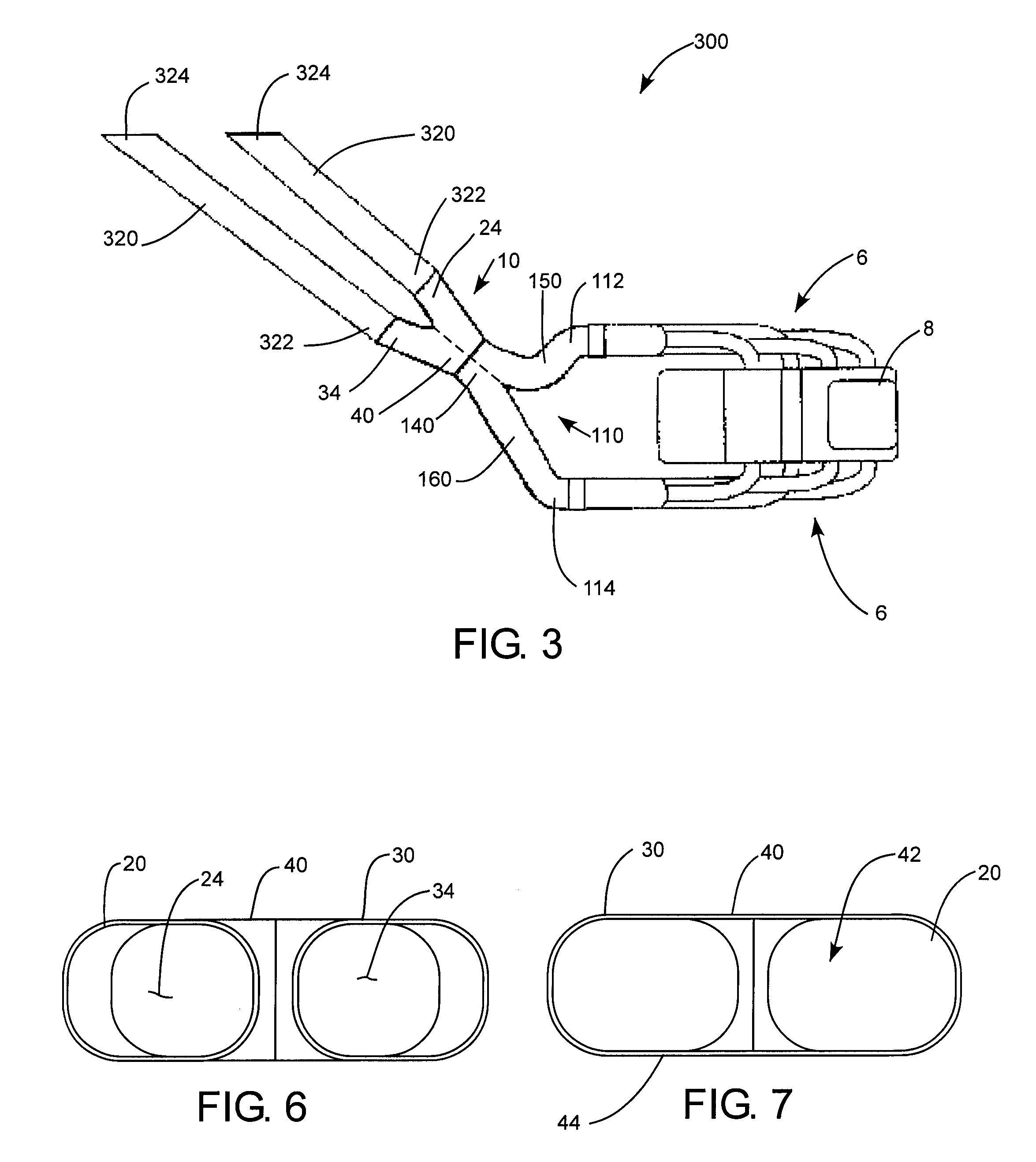
[0012]The present invention provides for the attachment of two tailpipes to a Y-pipe assembly to provide the advantages of the Y-pipe assembly to an exhaust system using two tailpipes such as two customary tailpipes or two boom tube exhaust pipe tailpipes. The invention comprises a Y-pipe splitter having a single inlet for attachment to the single outlet of a Y-pipe assembly normally attached to a single tailpipe. However, rather than attaching a single tailpipe to the single outlet of the Y-pipe assembly, the single inlet of the Y-pipe splitter attaches to the single outlet of the Y-pipe assembly. The Y-pipe splitter has two outlets and a tailpipe, such as a customary tailpipe or a boom tube exhaust pipe, is attached to each of the Y-pipe splitter outlets to provide an exhaust system having two tailpipes. The Y-pipe assembly is attached to the respective ends of a pair of primary exhaust pipes or header assemblies which lead exhaust gasses from the engine of a race car or other motor vehicle to the Y-pipe assembly. The Y-pipe assembly then takes the exhaust gases from the separate primary exhaust pipes and combines them in a flattened merged outlet portion to which a single boom tube type or other type tail exhaust pipe is normally connected. With the current invention, rather than connecting a tailpipe to the single outlet of the Y-pipe assembly, the single inlet of the Y-pipe splitter of the present invention is attached to the single outlet end of the Y-pipe assembly. The Y-pipe splitter is configured to split into two outlet openings to attach to inlets of a pair of exhaust pipes which mount to the bottom portion of the frame or chassis of the motor vehicle as tailpipes. Thus, while the Y-pipe assembly takes the exhaust gases from the separate primary exhaust pipes and combines them in a flattened merged portion which reduces exhaust pressure peaks in the exhaust system and reduces back pressure build up in the system, the Y-pipe splitter splits the exhaust from the flatten merged portion of the Y-pipe assembly and splits it again into two separate exhaust streams which exhaust to the atmosphere through the two exhaust pipes attached to the two outlets of the Y-pipe splitter. The combination of the Y-pipe assembly, along with the Y-pipe splitter and two exhaust pipes can provide the same improved ground clearance for the motor vehicle as the Y-pipe assembly and single exhaust pipe of my prior U.S. Pat. No. 6,478,340, as well as the advantages of reduced exhaust pressure peaks and reduced back pressure provided by the Y-pipe assembly and single exhaust pipe.
[0015]As a pressure pulse of exhaust gasses flows through one of the secondary exhaust pipes of the Y-pipe assembly and into the merged outlet portion, the inertia of the accelerating flow of exhaust gasses passing the opening thereinto of the other secondary exhaust pipe, a partial vacuum or lower pressure is briefly created within such other secondary exhaust pipe. When the next cylinder exhausts into such other secondary exhaust pipe forming a pressure pulse of exhaust gasses, the flow thereof is accelerated due to the lower pressure therein created by the previous pressure pulse such that more exhaust is removed from the exhausting engine cylinder. This increased removal of exhaust gasses from the cylinders of the engine improves engine performance by allowing space for a larger amount of fresh fuel / air mixture to enter the cylinder for the next firing of the cylinder. The Y-pipe splitter works in conjunction with the Y-pipe assembly to provide a joined inlet portion into the Y-pipe splitter into which the exhaust gases flow from the outlet portion of the Y-pipe assembly as they would into a single boom tube type exhaust tailpipe from where the splitter tailpipe sections of the Y-pipe splitter direct the flow and control the expansion of exhaust gasses to direct the exhaust gases to the pair of separate tailpipes. The single outlet of the Y-pipe assembly and the single inlet of the Y-pipe splitter allow controlled mixing of the exhaust gasses therebetween for fine tuning of the exhaust flows.

Problems solved by technology

Likewise, such race cars typically have very stiff suspension systems which do not allow the car to travel as great a distance up and down nor side-to-side as a standard production car, thereby allowing less clearance between the car body and the ground.
One of the problems encountered in lowering the race car closer to the race track is providing sufficient clearance between the car body and the race track for the car's exhaust system which is one of the lowest hanging components of a race car.
The problem is particularly acute on cars which race on oval race tracks, such as stock cars.
Unfortunately, side exhaust pipes complicate ground clearance problems because the minimum ground clearance of the exhaust system typically occurs where the exhaust pipes cross under the longitudinally-extending main frame members of the chassis at the sides of the car.
However, since many cars are fueled on the left side, the exhaust pipes usually now extend to the right side of the car, the side with least clearance, to reduce the chances of fuel spilling onto the hot exhaust pipes during fueling and igniting to cause a fire.
The Y-pipe assembly of my U.S. Pat. No. 6,478,340 provides improved performance of race car engines and an improved exhaust system configuration for providing exhaust system clearance, but is not designed for use with two tailpipes.

Method used


Image

  • Y splitter for exhaust systems
  • Y splitter for exhaust systems
  • Y splitter for exhaust systems

Examples


Embodiment Construction

[0026]Reference will now be made to the exemplary embodiments illustrated in the drawings, and specific language will be used herein to describe the same. It will nevertheless be understood that no limitation of the scope of the invention is thereby intended. Alterations and further modifications of the inventive features illustrated herein, and additional applications of the principles of the inventions as illustrated herein, which would occur to one skilled in the relevant art and having possession of this disclosure, are to be considered within the scope of the invention.

[0027]As illustrated in FIGS. 1-3, a Y-pipe splitter, indicated generally at 10, is shown in accordance an embodiment of the present invention for attachment to an end of a Y-pipe assembly 110 (FIG. 2). The Y-pipe assembly is attachable to primary exhaust pipes or header assemblies 6 (FIG. 3) which lead exhaust gasses from the engine 8 (FIG. 3) of a motor vehicle. The Y-pipe splitter 10 is also attachable to an i...


PUM


Abstract

A Y-pipe splitter for use on race cars, such as stock cars which race on oval tracks and sports cars which race on road course tracks, mounts to the lower frame or chassis of the car, and routes exhaust gasses from a Y-pipe assembly to a pair of tail pipes extending to the side of the car while providing improved ground clearance. The Y-pipe splitter includes first and second splitter tail pipe sections of a generally flattened oval cross-section with a longitudinally beveled inlet portions connectable to an outlet of the Y-pipe assembly and an outlet portion connectable to one of the tail pipes. The beveled inlet portions of the splitter tail pipe sections are affixed together along a respective edge of each thereof so as to merge together with respective centerlines thereof at an oblique angle to a single inlet opening which is connectable to the outlet opening of the Y-pipe assembly by affixing thereto.

Description

PRIORITY CLAIM[0001]Priority is claimed to U.S. Provisional Patent Application Ser. No. 61 / 009,764 filed Dec. 31, 2007, which is hereby incorporated herein by reference in its entirety.BACKGROUND OF THE INVENTION[0002]1. Field of the Invention[0003]The invention is in the field of exhaust systems for automobiles, and more specifically thin exhaust pipes for increased ground clearance on racing cars, such as stock cars, formula cars, sports cars, and the like, used on oval tracks or road course tracks.[0004]2. Related Art[0005]Race cars used in automobile racing are typically constructed such that only a minimal amount of clearance is maintained between the underside of the car and the surface of the roadway or track. This is done to lower the center of gravity of the car so as to improve car handling, increase resistance to rolling over, and minimize the drag due to air passing under the car. Likewise, such race cars typically have very stiff suspension systems which do not allow th...

Claims


Application Information

Patent Timeline
Patent Type & Authority Patents(United States)
IPC IPC(8): B60K13/00B60K13/04
CPCB60K13/04F01N13/08F01N2340/04
Inventor BUTLER, BOYD L.
Owner BUTLER BOYD L
Why Eureka
Try Eureka