Process for making nitrogen by air separation or making nitrogen and simultaneously producing oxygen in attached manner

An air separation and nitrogen technology, which is applied in cold treatment separation, refrigeration and liquefaction, liquefaction and other directions, can solve the problems of high energy consumption in the operation of the device and low extraction rate of process products, and achieve the requirements of reducing energy consumption, low energy consumption and low discharge pressure. Effect

Inactive Publication Date: 2012-07-04
开封黄河空分集团有限公司
View PDF7 Cites 12 Cited by
  • Summary
  • Abstract
  • Description
  • Claims
  • Application Information

AI Technical Summary

Problems solved by technology

[0003] The purpose of the present invention is to provide a process for producing nitrogen by air separation or producing nitrogen while prod

Method used


Image

  • Process for making nitrogen by air separation or making nitrogen and simultaneously producing oxygen in attached manner
  • Process for making nitrogen by air separation or making nitrogen and simultaneously producing oxygen in attached manner

Examples


Embodiment 1

[0034] Production of nitrogen 30500 Nm 3 / h

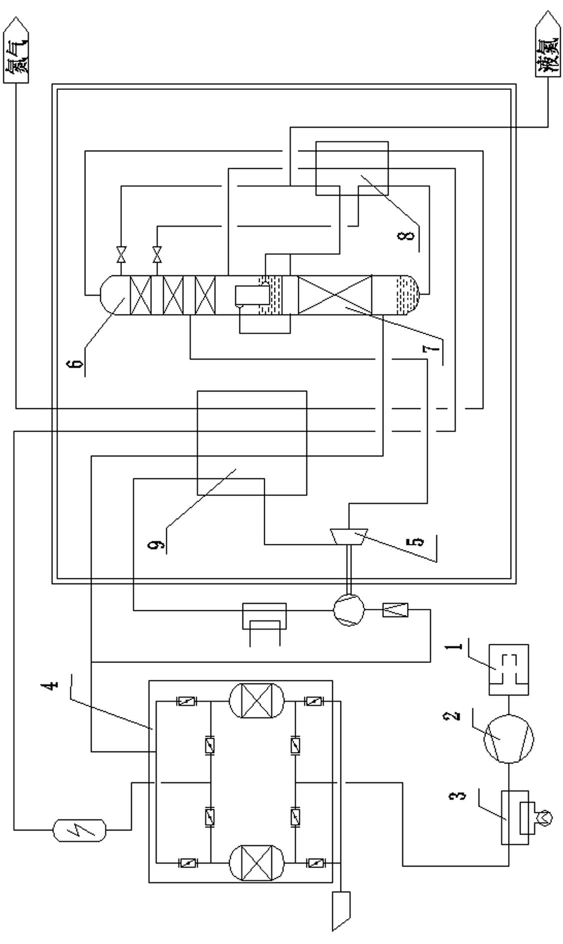
[0035] combine figure 1 , feed air 43000 Nm 3 / h The dust and impurities in the air are removed by the air filter 1, and then compressed to 0.41MPa by the air compressor 2, and then the air temperature is reduced to 5-8°C by the pre-cooling system 3, and the free water is separated before entering the purification system 4. Remove H 2 O.CO 2 、C 2 h 2 and other hydrocarbons.

[0036] The purified air is split into two paths: 9500 Nm of which 3 The air per hour enters the booster expander 5 for expansion and refrigeration. After expansion, the air enters the middle part of the upper rectification tower 6 to participate in rectification. You get nitrogen at the top and oxygen-enriched liquid air at the bottom.

[0037] The nitrogen obtained at the top of the lower rectification tower 7 enters the condensing evaporator at the bottom of the upper rectifying tower 6 as a heat source and is cooled into liquid nitrogen by the oxyg...

Embodiment 2

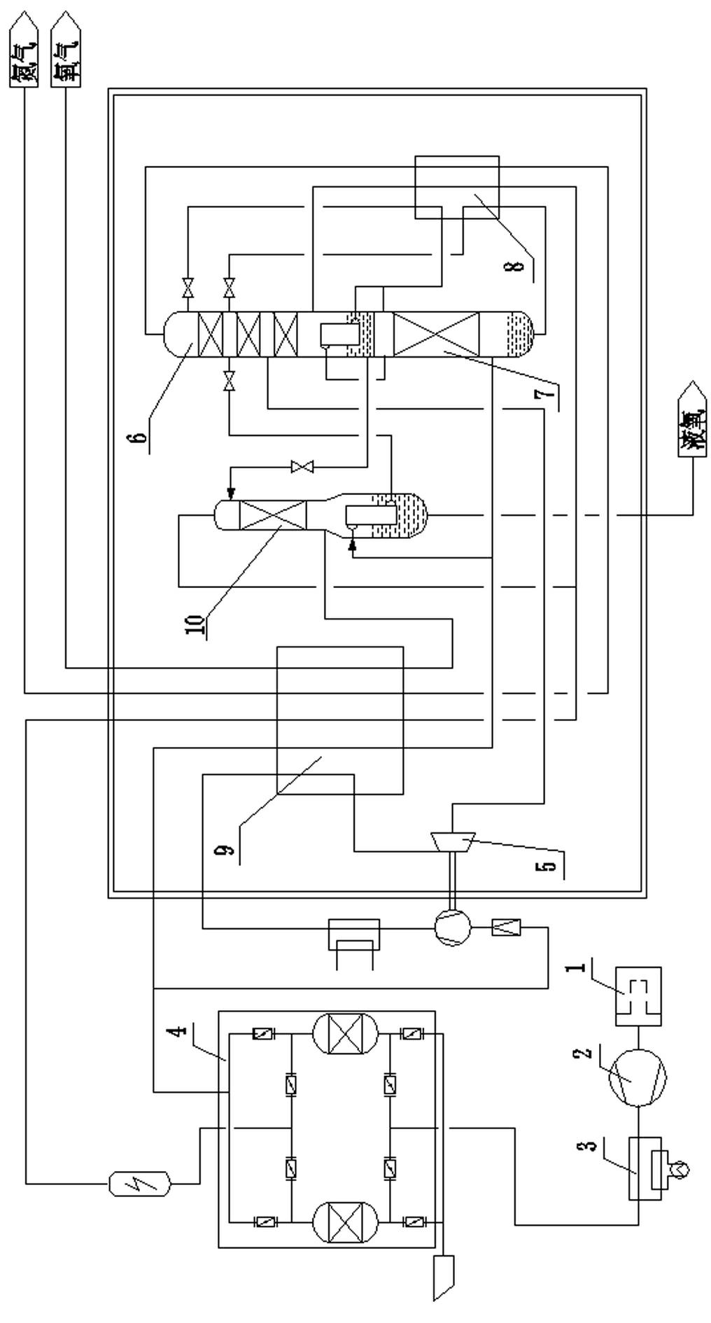
[0042] Nitrogen production: 25000 Nm 3 / h, liquid oxygen: 500 Nm 3 / h.

[0043] combine figure 2 , feed air 34000 Nm 3 / h The dust and impurities in the air are removed by the air filter 1, and then compressed to 0.41MPa by the air compressor 2, and then the air temperature is reduced to 5-8°C by the pre-cooling system 3, and the free water is separated before entering the purification system 4. Remove H 2 O.CO 2 、C 2 h 2 and other hydrocarbons.

[0044] The purified air is divided into two paths: 9000 Nm of which 3 The air per hour enters the expander 5 for expansion and refrigeration. After expansion, the air enters the middle part of the upper rectification tower 6 (with 60 trays of structured packing corresponding to the packing) to participate in rectification. The rest of the air is cooled to the saturation temperature and divided into two parts: 23700 Nm 3 The air per hour enters the lower rectification tower 7 as rising steam to participate in rectification, ...


PUM


Abstract

The invention belongs to the technical field of air separation and particularly relates to a process for making nitrogen by air separation or making nitrogen and simultaneously producing oxygen in an attached manner. The process comprises the following steps of: cooling purified air and introducing into a distillation system, wherein the distillation system at least is a secondary distillation system composed of an upper distillation tower and a lower distillation tower connected into a whole by a condensate evaporator; dividing the purified air into two paths, wherein one path is to introduce the purified air into an expander for expansion refrigeration and introducing expanded air into the middle part of the upper distillation tower, and the other path is to introduce the purified air into the lower distillation tower for distillation after the purified air is cooled to the saturation temperature; and finally obtaining a nitrogen product at the top part of the upper distillation tower. The process has the beneficial effects that an air compressor is low in exhaust pressure and low in energy consumption, so that the energy consumption requirements of a nitrogen production device by air separation are greatly reduced; the current requirements of energy conservation and emission reduction in China on high energy consuming industries are satisfied; and meanwhile, the extraction rate of the nitrogen can be up to 85-97%, and the energy consumption is 0.1-0.18 kWh/Nm3N2.

Description

technical field [0001] The invention belongs to the technical field of air separation, and in particular relates to a process for preparing nitrogen or oxygen by nitrogen by air separation. Background technique [0002] With the development of society and economy, in recent years, the application field of high-purity nitrogen equipment has been expanding, such as petrochemical, glass, rubber, building board, polysilicon, carbon fiber and other industries. The industry's demand for nitrogen and oxygen is constantly increasing, and at the same time, higher requirements for energy saving and consumption reduction are constantly being put forward. Therefore, in order to take the initiative in the market, it is necessary to increase the extraction rate of the product, reduce the energy consumption of the device operation, tap the energy-saving potential of the equipment operation, and at the same time make full use of the air as much as possible and extract nitrogen and oxygen fr...

Claims


Application Information

Patent Timeline
IPC IPC(8): F25J3/04
CPCF25J3/04303F25J3/04412F25J2200/34
Inventor 彭辉王好民刘中杰王玉磊
Owner 开封黄河空分集团有限公司
Why Eureka
Try Eureka