Eureka AIR delivers breakthrough ideas for toughest innovation challenges, trusted by R&D personnel around the world.

Method of replacing anchor bolts in wind turbine foundations

Active Publication Date: 2018-12-13
VESTAS WIND SYST AS
View PDF1 Cites 2 Cited by
  • Summary
  • Abstract
  • Description
  • Claims
  • Application Information

AI Technical Summary

Benefits of technology

The patent describes a method for replacing an anchor bolt used to support a wind turbine to a foundation. The method includes drilling a cavity in the lower tower flange and the rigid body around the anchor bolt, and inserting a replacement anchor bolt into the cavity to create a cavity. The replacement anchor bolt is then tensioned and coupled to the lower base flange. The method has technical effects including minimizing damage to the foundation and improving the efficiency of replacing anchor bolts.

Problems solved by technology

Foundations are designed to far exceed the life expectancy of the various wind turbine components, since replacement or repair is expensive and / or difficult.
However, like many structural components, the anchor bolts are conservatively designed with a built-in factor of safety designed to withstand such stresses.
However, if the anchor bolts do not maintain sufficient post-tensioning, the anchor bolts may begin to loosen.
Insufficient post-tensioning may cause the anchor bolts to move within the concrete foundation.
This may be visually apparent through cracks propagating in the concrete foundation over time.
Left unchecked, if the anchor bolts loosen to below a certain post-tensioning value, the resulting weakening of the concrete foundation may reduce of the life expectancy of the concrete foundation supporting the wind turbine.
However, repairing or replacing the foundation after wind turbine assembly and operation is costly and time-consuming, and cannot generally be performed while the wind turbine is actively operating (where the blades are actively rotating) or in standstill mode (where the blades are not rotating).

Method used


Image

  • Method of replacing anchor bolts in wind turbine foundations
  • Method of replacing anchor bolts in wind turbine foundations
  • Method of replacing anchor bolts in wind turbine foundations

Examples


Embodiment Construction

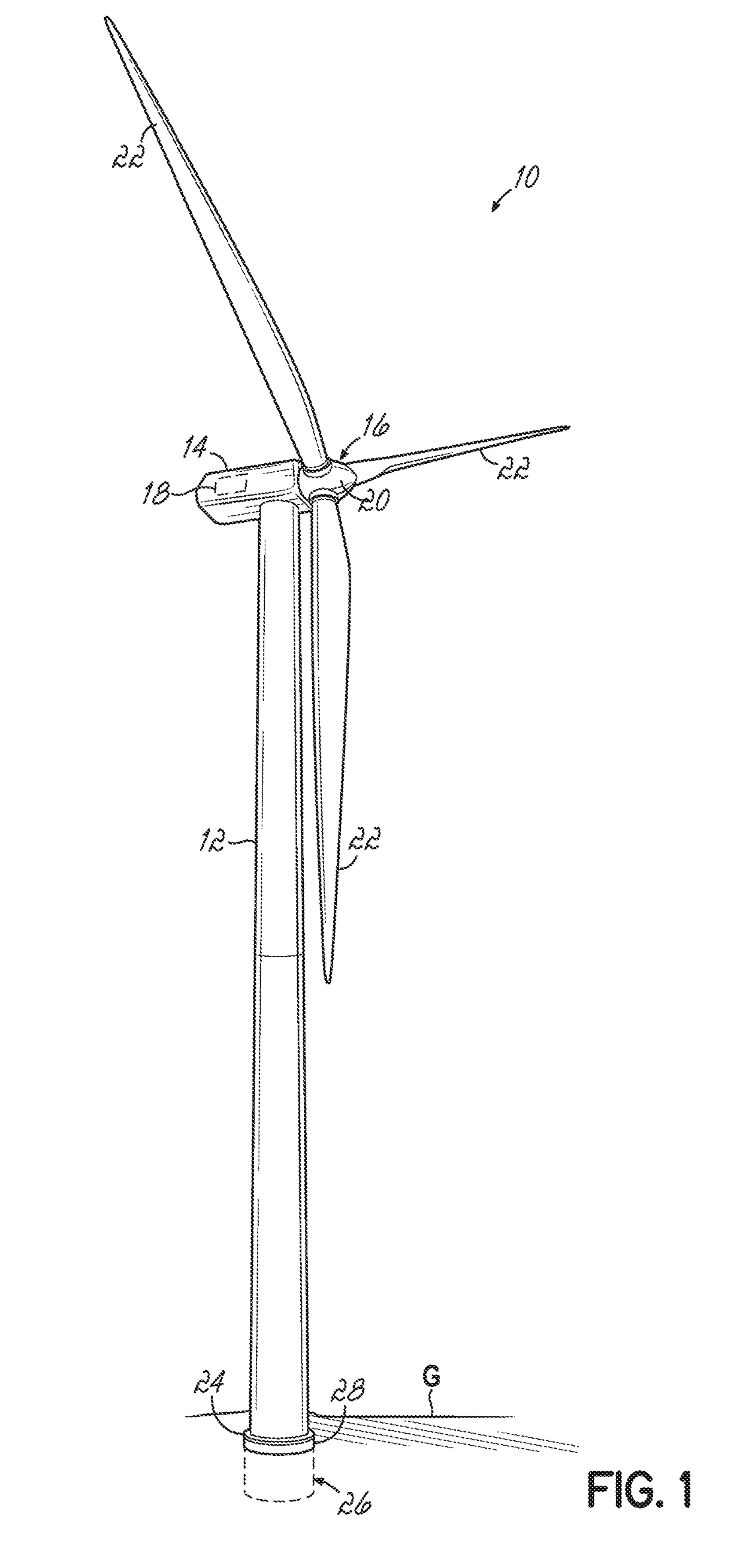
[0027]Referring to the figures, and to FIG. 1 in particular, an exemplary horizontal-axis wind turbine 10 generally includes a tower 12, a nacelle 14 disposed at the apex of the tower 12, and a rotor 16 operatively coupled to a generator 18 housed inside the nacelle 14. In addition to the generator 18, the nacelle 14 houses miscellaneous components required for converting wind energy into electrical energy and various components needed to operate, control, and optimize the performance of the wind turbine 10. The tower 12 supports the load presented by the nacelle 14, the rotor 16, and other components of the wind turbine 10 that are housed inside the nacelle 14. The tower 12 further operates to elevate the nacelle 14 and the rotor 16 to a height above ground level or sea level, as may be the case, at which faster moving air currents of lower turbulence are typically found.

[0028]The rotor 16 of the wind turbine 10 serves as the prime mover for the electromechanical system. Wind excee...


PUM


Abstract

A method of replacing an anchor bolt used to support a wind turbine to a foundation. The method includes providing the wind turbine and the foundation supporting the wind turbine. The foundation includes a lower base flange, at least one anchor bolt extending between the lower base flange and a lower tower flange of the wind turbine, and a rigid body at least partially formed around the at least one anchor bolt. The method further includes drilling a core in the lower tower flange and the rigid body circumferentially around the anchor bolt and removing the anchor bolt and the core to create a cavity. The method further includes inserting a replacement anchor bolt into the cavity and coupling the replacement anchor bolt to the lower base flange. The replacement anchor bolt may then be tensioned.

Description

TECHNICAL FIELD[0001]The present invention relates generally to wind turbines, and more particularly to methods of replacing one or more anchor bolts in a foundation used to support the wind turbine.BACKGROUND[0002]Wind turbines are used to produce electrical energy using a renewable resource and without combusting a fossil fuel. Generally, a wind turbine converts kinetic energy from the wind into electrical power. A horizontal-axis wind turbine generally includes a tower, a nacelle located at the apex of the tower, and a rotor having a plurality of blades and supported in the nacelle by a shaft. The shaft couples the rotor either directly or indirectly with a generator, which is housed inside the nacelle. Consequently, as wind forces the blades to rotate, electrical energy is produced by the generator.[0003]Horizontal-axis wind turbines may be anchored on land by securing a lower portion, such as a lower tower flange, of the wind turbine tower to a foundation that extends into the ...

Claims


Application Information

Patent Timeline
IPC IPC(8): F03D80/50E02D27/42E02D37/00F03D13/20
CPCF03D80/50E02D27/425E02D37/00F03D13/22F05B2230/80F05B2260/301F05B2240/912Y02E10/72Y02E10/728Y02P70/50
Inventor SANDVAD, INGEMANN HVASJENSEN, SOREN P.
Owner VESTAS WIND SYST AS
Why Eureka
Eureka Blog
Learn More