Electronic device cooling system

a technology for electronic devices and cooling systems, which is applied in the direction of computer control, process and machine control, instruments, etc., can solve the problems of troublesome operation, difficulty in complete removal of oil adhesion to electronic devices, and obstacle to the maintenance work of electronic devices, etc., to suppress the height dimension of the device, facilitate the collection of accidentally leaked coolant, and high durability

Inactive Publication Date: 2018-12-13
EXASCALER
View PDF5 Cites 2 Cited by
  • Summary
  • Abstract
  • Description
  • Claims
  • Application Information

AI Technical Summary

Benefits of technology

[0027]According to an aspect of the present invention, it is possible to provide the cooling system which facilitates collection of the accidentally leaked coolant.
[0028]According to another aspect of the present invention, it is possible to provide the cooling system capable of suppressing the height dimension of the device for temporarily accumulating the leaked coolant until it is collected.
[0029]According to still another aspect of the present invention, it is possible to provide the cooling system which is highly durable against externally exerted strong impact and vibration caused by such disaster as earthquake.
[0030]The above-described or any other objects and advantages will be clearly understood in reference to the following description of the embodiments. The description herein is for an illustrative purpose, and therefore, the present invention is not limited to those embodiments.

Problems solved by technology

However, the use of the synthetic oil with high viscosity for the liquid coolant causes difficulty in complete removal of the oil adhering to the electronic device when it is taken from the oil immersion rack.
This may be an obstacle to the maintenance work for the electronic device (specifically, for example, adjustment, inspection, repair, replacement, extension).
Furthermore, the trouble in the operation caused by the synthetic oil leakage has been reported.
Specifically, the synthetic oil in use will corrode the packing or the like that constitutes the cooling system in a short period of time, resulting in the synthetic oil leakage.

Method used


Image

  • Electronic device cooling system
  • Electronic device cooling system
  • Electronic device cooling system

Examples


Embodiment Construction

[0038]Preferred embodiments of the cooling system according to the present invention will be described in detail based on the drawings.

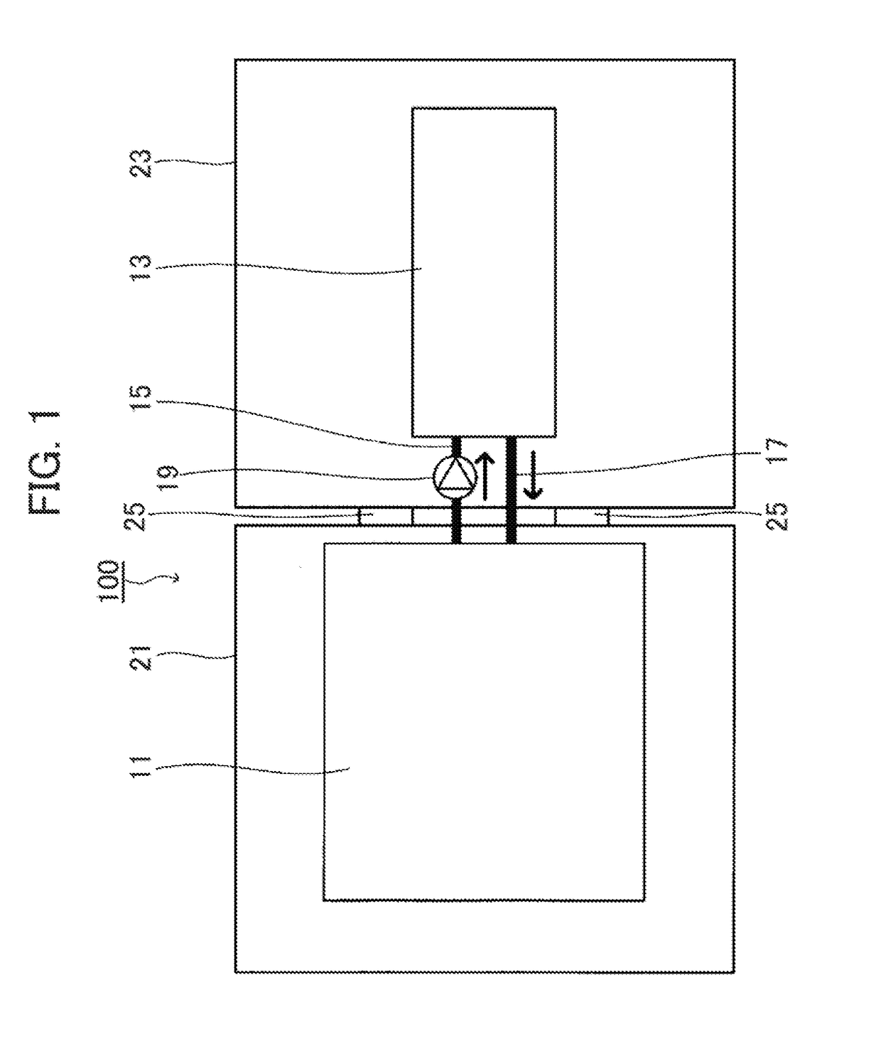
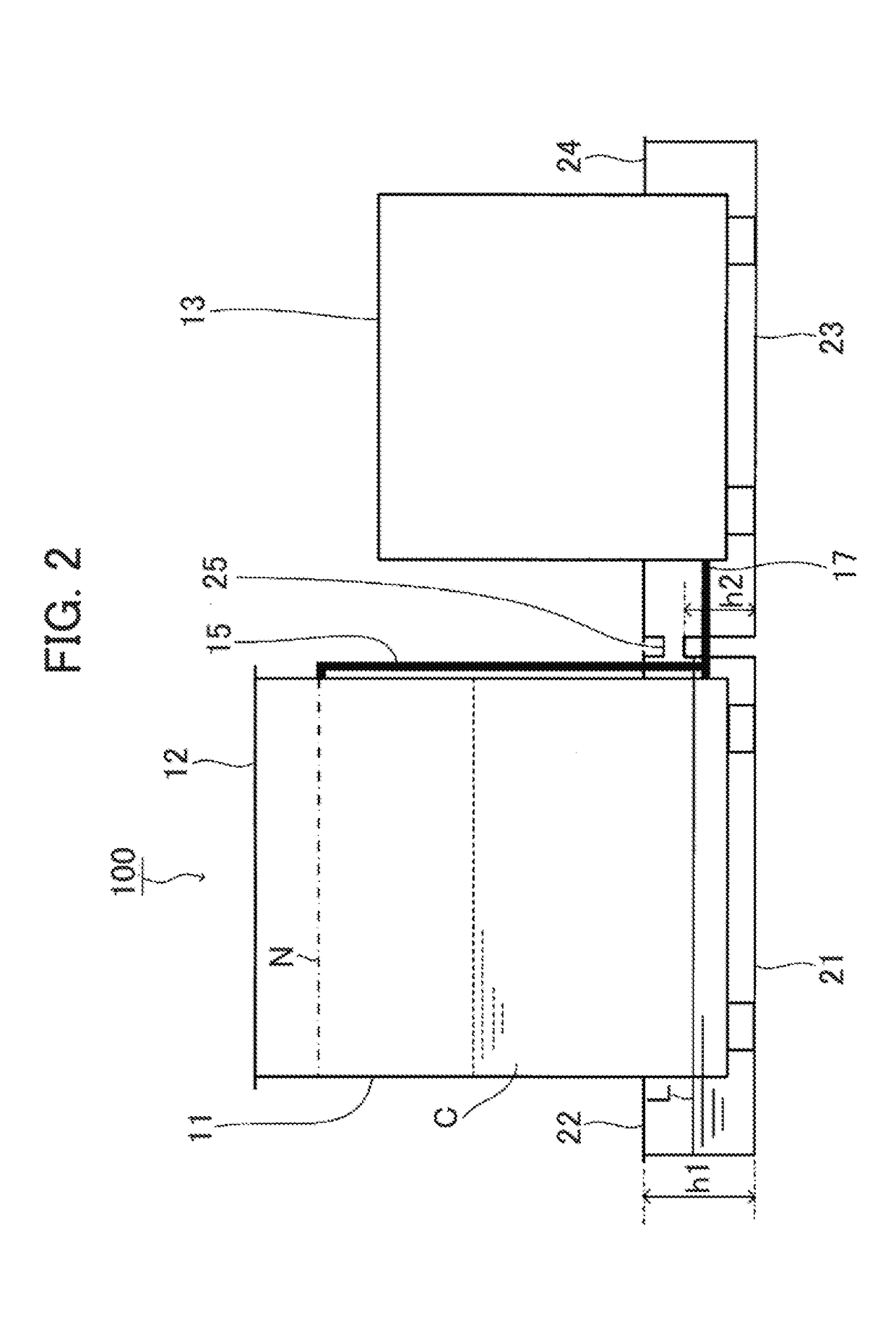
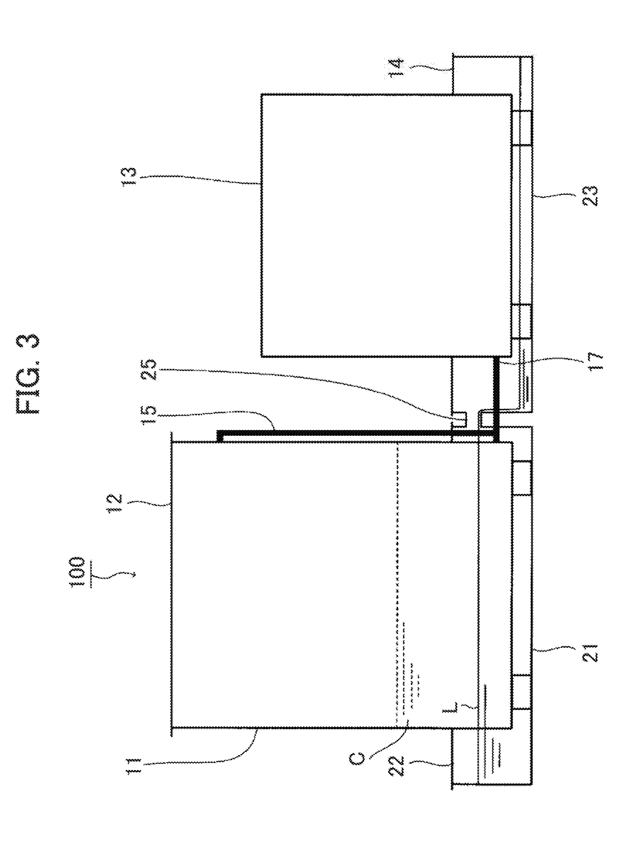
[0039]Referring to FIGS. 1 and 2, a cooling system 100 according to an embodiment includes a cooling tank 11 containing a coolant C, a leakage receiving portion 21 disposed between the cooling tank 11 and a floor surface, another leakage receiving portion 23 disposed between a heat exchanger 13 and an installation surface, and a passage 25 for connecting the leakage receiving portions 21 and 23. A plurality of electronic devices (not shown) are immersed in the coolant C that circulates in the cooling tank 11 so as to be directly cooled. Preferably, the cooling tank 11 has an open space. The cooling tank 11 having the “open space” described in the specification includes the cooling tank with a simple sealing structure sufficient to secure maintainability of the electronic device. The simple sealing structure refers to the one that allows a top plate 1...


PUM


Abstract

A cooling system 300 configured to directly cool an electronic device immersed in a coolant includes a cooling tank 11 containing the coolant C, and a leakage receiving portion 41 disposed between the cooling tank 11 and a floor surface so as to receive the coolant C leaked from the cooling tank 11. The leakage receiving portion 41 includes a distribution plate 40 for distributing a load applied from the cooling tank 11, a closed side wall disposed on the distribution plate to enclose the cooling tank 11, and a lid member 42 for covering an upper opening between the closed side wall and the cooling tank 11. The system facilitates collection of the accidentally leaked coolant, and ensures to keep the low height of the device for temporarily accumulating the leaked coolant L until it is collected.

Description

TECHNICAL FIELD[0001]The present invention relates to a cooling system for electronic devices. More specifically, the present invention relates to the cooling system for electronic devices, which is configured to efficiently cool the electronic devices such as the supercomputer, and the data center which are required to exert super-high performances and stable operations while generating the high heating value.BACKGROUND ART[0002]Conventionally, the process for cooling the supercomputer and the data center has been performed through two different methods, that is, the air cooling method and the liquid cooling method. In general, the cooling efficiency of the liquid cooling method is better than that of the air cooling method because liquid exhibits higher heat transfer performance than air. For example, the liquid immersion cooling system using synthetic oil has been employed for the supercomputer called “TSUBAME-KFC” constructed by Tokyo Institute of Technology. However, the use of...

Claims


Application Information

Patent Timeline
Patent Type & Authority Applications(United States)
IPC IPC(8): G06F1/20G05B15/02H05K7/20
CPCG06F1/206G05B15/02H05K7/20763H05K7/20236H05K7/20272G06F1/20H01L2224/16225H05K7/20781G06F2200/201H05K7/20
Inventor SAITO, MOTOAKI
Owner EXASCALER
Why Eureka
Try Eureka