Steering device

a technology of steering device and peripheral surface, which is applied in the direction of steering parts, vehicle components, transportation and packaging, etc., can solve the problems of backlash in engagement between the outer peripheral surface of the fastening shaft and the pressing load, and achieve the effect of reducing the concentration of stress

Active Publication Date: 2018-12-20
JTEKT CORP +1
View PDF16 Cites 6 Cited by
  • Summary
  • Abstract
  • Description
  • Claims
  • Application Information

AI Technical Summary

Benefits of technology

[0005]However, in such a case, there may be backlash in engagement between the outer peripheral surface of the fastening shaft and an inner peripheral surface of the cylindrical member. In that case, when the release member and the tooth member are disengaged from each other in a transition from an unlocked state to a locked state, energizing reaction force of the release member against energizing force of the energizing member is released instantly, and sound of hammering can be generated between the fastening shaft and the cylindrical member. An object of the disclosure is to provide a steering device that is able to restrain generation of sound of hammering.
[0007]In the steering device according to the above aspect, in an unlocked state, the release portion of the release member is engaged with the second tooth member, thus holding the second tooth member in a non-meshed state against the energizing member. During a transition from the unlocked state to a locked state, when the release portion and the second tooth member are disengaged from each other, energizing reaction force of the release member against energizing force of the energizing member is released instantly. Meanwhile, because of the projecting portion that is provided in at least one of the first flat portion of the outer peripheral surface of the fastening shaft and the second flat portion of the inner peripheral surface of the cylindrical portion of the release member, and is elastically engaged with the other one of the first flat portion and the second flat portion, backlash between both of the flat portions is restrained. Therefore, with the steering device according to the above aspect, it is possible to restrain generation of sound of hammering between both of the flat portions when the energizing reaction force is released.
[0009]With the steering device according to the above aspect, at the time of assembly, when the cylindrical portion of the release member is fitted and assembled to the fastening shaft, it is possible to elastically deform the cylindrical portion easily by the action of the slit extending in the axis direction of the cylindrical portion so as to assemble the cylindrical portion to the fastening shaft.
[0011]With the steering device according to the above aspect, even if a damage or the like happens in the circumferentially-discontinuous region that is discontinuous in the circumferential direction because the slit is provided in the cylindrical portion of the release member, the cylindrical portion is prevented from falling off from the fastening shaft by the circumferentially continuous region that is continuous in the circumferential direction of the cylindrical portion.
[0013]In the steering device according to the above aspect, in the non-meshed state, engagement reaction force applied to the cylindrical portion of the release member by the second tooth member via the release portion acts in a direction in which the second flat portion of the opposite-side circumferential region is separated from the first flat portion of the fastening shaft, the second flat portion being on the opposite side with respect to the release portion side and provided with the projecting portion. Therefore, with the steering device according to the above aspect, it is possible to reduce a load applied to the projecting portion. Accordingly, permanent deformation of the projecting portion is restrained, and it is thus possible to restrain generation of sound of hammering between the first and the second flat portions for a long period of time.
[0015]In the steering device according to above aspect, in the curved edge portion provided in the cylindrical portion, the curved edge portion defining the closed end of the slit extending in the axis direction, stress applied to a first adjacent portion tends to be higher than stress applied to a second adjacent portion. The first adjacent portion is adjacent to the opposite-side circumferential region that is disposed on the opposite side with respect to the release portion side and provided with the projecting portion, and the second adjacent portion is adjacent to the release portion-side circumferential region. Therefore, in the above aspect, in the curved edge portion that defines the closed end of the slit, the curvature radius of the first adjacent portion is larger than the curvature radius of the second adjacent portion. Therefore, in the steering device according to the above aspect, in the curved edge portion, it is possible to alleviate concentration of stress on the first adjacent portion.

Problems solved by technology

However, because of a manufacturing error, a load applied when the tooth member is pressed against the tooth portion can vary, thus making the pressing load excessive or increasing an operation load on the operation lever during the lock operation.
However, in such a case, there may be backlash in engagement between the outer peripheral surface of the fastening shaft and an inner peripheral surface of the cylindrical member.

Method used


Image

  • Steering device
  • Steering device
  • Steering device

Examples


Embodiment Construction

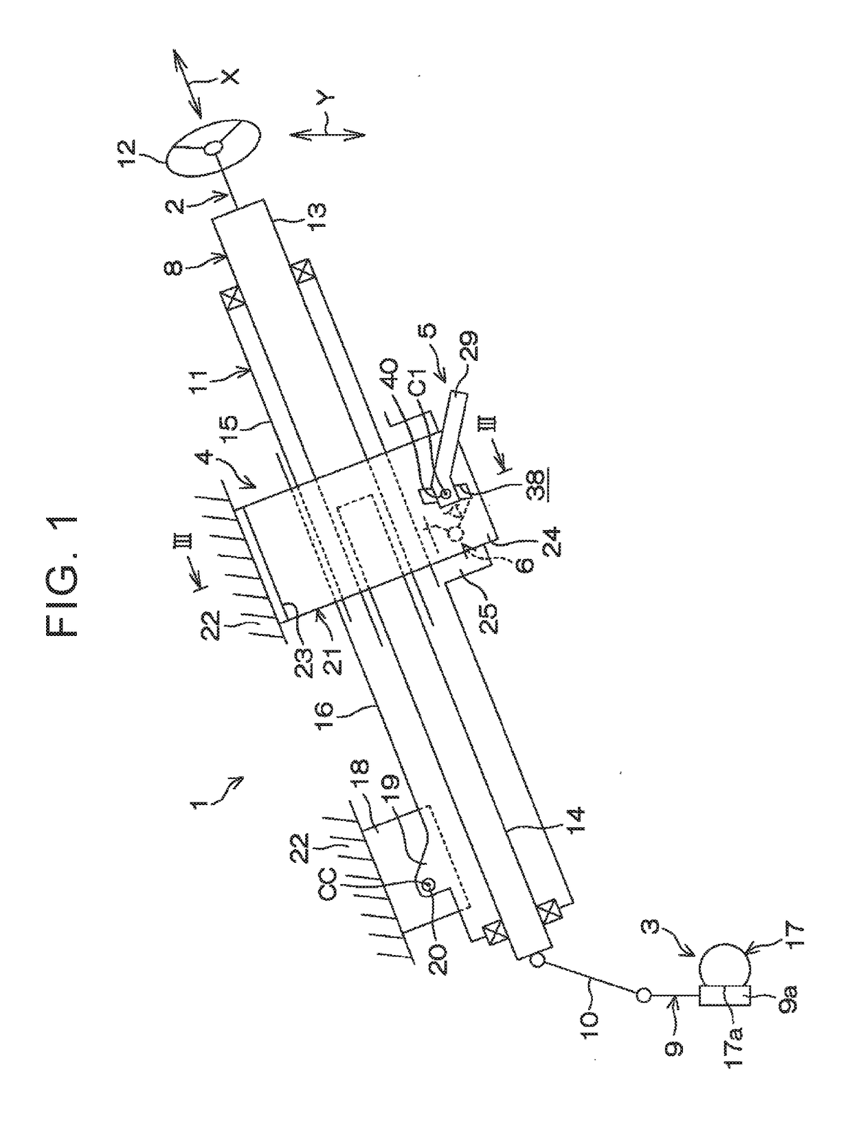
[0026]FIG. 1 is a partially sectional schematic side view of a basic structure of a steering device according to an embodiment of the disclosure. With reference to FIG. 1, a steering device 1 includes a steering input mechanism 2, a steering output mechanism 3, a support mechanism 4, a fastening mechanism 5, and a tooth locking mechanism 6. The steering input mechanism 2 includes a column shaft 8, a pinion shaft 9, an intermediate shaft 10, and a column jacket 11. The intermediate shaft 10 is interposed between the column shaft 8 and the pinion shaft 9. The column shaft 8 is inserted in the column jacket 11, and the column jacket 11 thus supports the column shaft 8 so that the column shaft 8 is able to rotate.

[0027]The column shaft 8 includes an upper shaft 13 connected with a steering wheel 12, and a lower shaft 14 connected with the intermediate shaft 10. The upper shaft 13 and the lower shaft 14 are fitted to each other in a manner of, for example, spline-fitting or serration-fit...


PUM


Abstract

A steering device includes a column shaft, a column jacket, a fastening mechanism including a fastening shaft having a first flat portion, a first tooth member, a second tooth member, an energizing member, and a release member including: a cylindrical portion having a second flat portion; and a release portion, wherein: the release member is configured to cause the release portion to be engaged with the second tooth member; and a projecting portion formed on at least one of the first flat portion and the second flat portion is elastically engaged with the other one of the first flat portion and the second flat portion and restrain backlash between the first flat portion and the second flat portion.

Description

INCORPORATION BY REFERENCE[0001]The disclosure of Japanese Patent Application No. 2017-116936 filed on Jun. 14, 2017 including the specification, drawings and abstract is incorporated herein by reference in its entirety.BACKGROUND1. Technical Field[0002]The disclosure relates to a steering device.2. Description of Related Art[0003]Japanese Unexamined Patent Application Publication No. 2007-83936 (JP 2007-83936 A) discloses a steering device with a telescoping-adjustment ability. In the steering device, a tooth portion is provided in a movable-side jacket on an upper side, and a tooth member is provided in a fixed-side jacket on a lower side. The fixed-side jacket supports the tooth member so that the tooth member is able to vertically swing about a pin. The fixed-side jacket supports an adjustment bolt (a fastening shaft) that rotates integrally with an operation lever, and a pole (a cylindrical member) is fitted onto the fastening shaft. On an outer periphery of the cylindrical mem...

Claims


Application Information

Patent Timeline
Patent Type & Authority Applications(United States)
IPC IPC(8): B62D1/184B62D1/189
CPCB62D1/184B62D1/189B62D1/185
Inventor SUGIURA, TOMONORIKIKUIRI, KENTAROISHIMURA, SHOJIOOSONO, NAOHIROISHII, YUUJIITO, KOSUKEHOSHINO, SHIGERU
Owner JTEKT CORP
Why Eureka
Try Eureka