Combustion Section Heat Transfer System for a Propulsion System

Active Publication Date: 2018-12-20
GENERAL ELECTRIC CO
View PDF12 Cites 30 Cited by
  • Summary
  • Abstract
  • Description
  • Claims
  • Application Information

AI Technical Summary

Benefits of technology

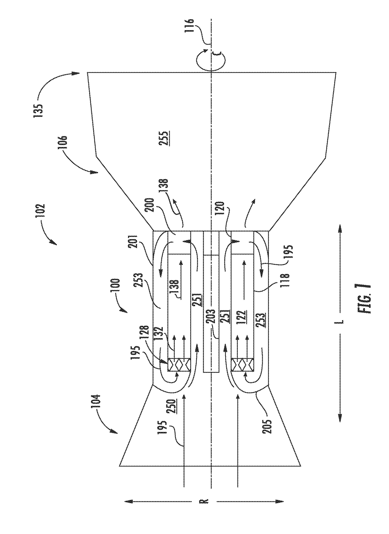
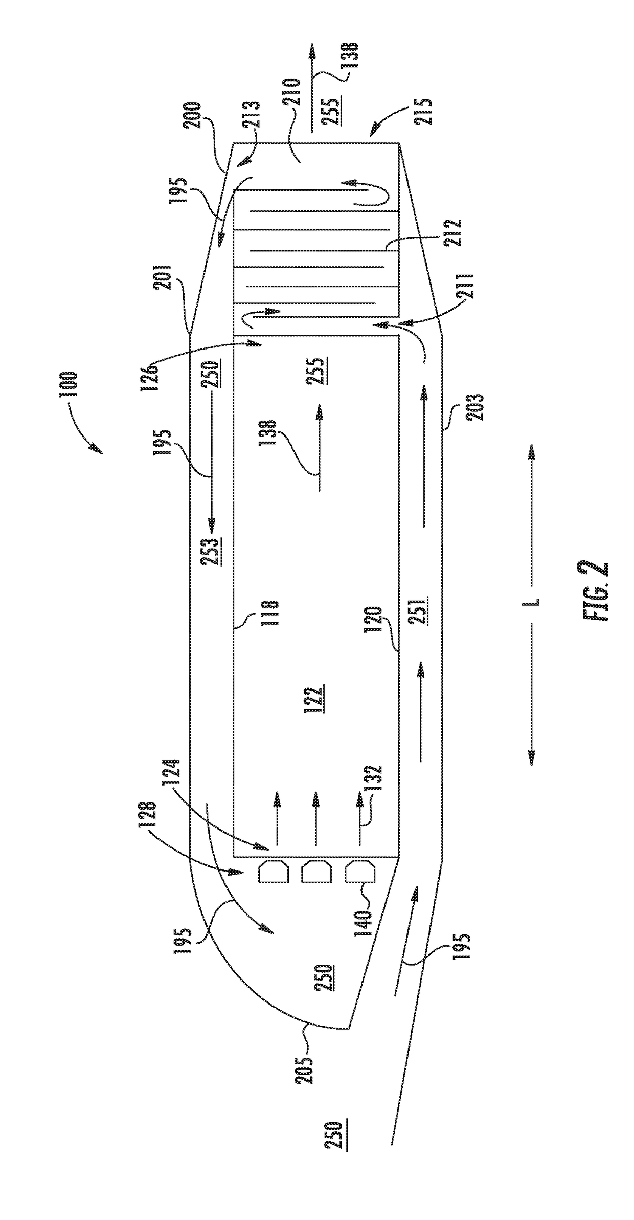
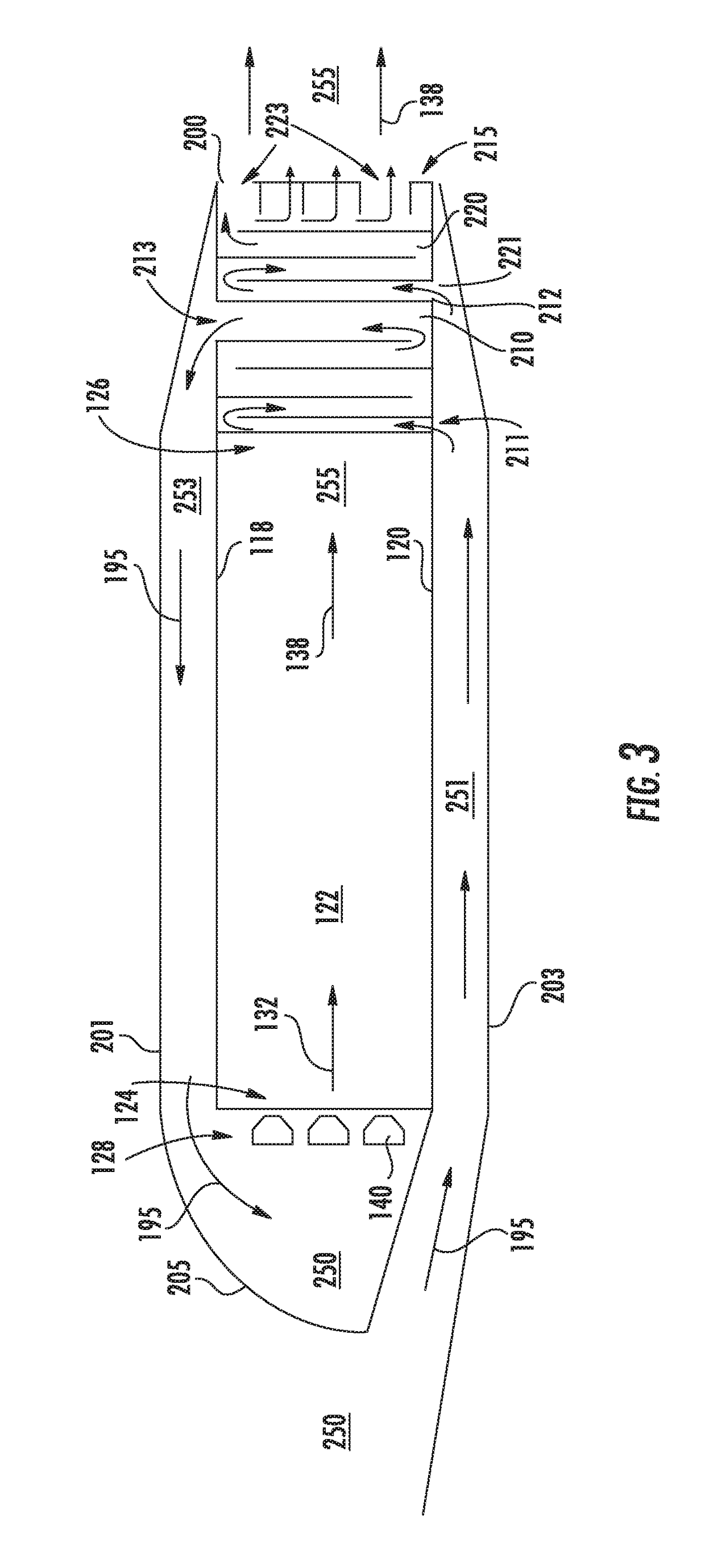
[0013]In still various embodiments, the turbine nozzle defines a second cooling circuit within the plurality of airfoils. The second cooling circuit is in direct fluid communication with one or more of the ID primary flowpath and the OD primary flowpath. In one embodiment, the second cooling circuit is disposed at a trailing edge of the plurality of airfoils. In another embodiment, the propulsion system defines a hot gas path downstream of the combustion chamber, in which the second cooling circuit is in direct fluid communication with the hot gas path.
[0014]In various embodiments, a channel structure is defined in one or more of the ID primary flowpath and the OD primary flowpath. The channel structure is in direct fluid communication with the first cooling circuit. In one embodiment, the channel structure comprises one or more channel walls extended at least along the longitudinal direction defining one or more cooling channels in fluid communication with the first cooling circuit and the primary flowpath. In another embodiment, the one or more channel walls are coupled to the one or more cooling circuit walls. The first cooling circuit is in direct fluid communication with the cooling channels.
[0015]In various embodiments, a heat exchanger is disposed within the primary flowpath. In one embodiment, the heat exchanger is disposed within one or more of an ID primary flowpath, a second ID primary flowpath, an OD primary flowpath, and a second OD primary flowpath.
[0016]In another embodiment, a support member is extended at least partially along the radial direction from one or more of the outer casing and the inner casing to one or more of the outer wall and the inner wall. In one embodiment, the support member defines a passage through which a flow of oxidizer from an upstream inlet section enters one or more of an inner diameter (ID) primary flowpath and an outer diameter (OD) primary flowpath.

Problems solved by technology

As such, propulsion systems must balance utilizing air from the primary flowpath for mitigating structural deterioration of the turbine nozzle with performance and efficiency losses due to removing air from mixture with a fuel for generating combustion gases.

Method used


Image

  • Combustion Section Heat Transfer System for a Propulsion System
  • Combustion Section Heat Transfer System for a Propulsion System
  • Combustion Section Heat Transfer System for a Propulsion System

Examples


Embodiment Construction

[0027]Reference now will be made in detail to embodiments of the invention, one or more examples of which are illustrated in the drawings. Each example is provided by way of explanation of the invention, not limitation of the invention. In fact, it will be apparent to those skilled in the art that various modifications and variations can be made in the present invention without departing from the scope or spirit of the invention. For instance, features illustrated or described as part of one embodiment can be used with another embodiment to yield a still further embodiment. Thus, it is intended that the present invention covers such modifications and variations as come within the scope of the appended claims and their equivalents.

[0028]As used herein, the terms “first”, “second”, and “third” may be used interchangeably to distinguish one component from another and are not intended to signify location or importance of the individual components.

[0029]The terms “upstream” and “downstre...


PUM


Abstract

The present disclosure is directed to a propulsion system including an annular inner wall and an annular outer wall, a nozzle assembly, a turbine nozzle, and an inner casing and an outer casing. The inner wall and outer wall together extend at least partially along a longitudinal direction and together define a combustion chamber inlet, a combustion chamber outlet, and a combustion chamber therebetween. The nozzle assembly is disposed at the combustion inlet and provides a mixture of fuel and oxidizer to the combustion chamber. The turbine nozzle defines a plurality of airfoils in adjacent circumferential arrangement disposed at the combustion chamber outlet. The turbine nozzle is coupled to the outer wall and the inner wall. The inner casing is disposed inward of the inner wall and the outer casing is disposed outward of the outer wall. Each of the inner casing and the outer casing are coupled to the turbine nozzle. A primary flowpath is defined between the inner casing and the inner wall, through the turbine nozzle, and between the outer casing and the outer wall, and in fluid communication with the combustion chamber.

Description

FIELD[0001]The present subject matter relates generally to a system of heat transfer for a combustion section of a propulsion system.BACKGROUND[0002]Conventional combustion systems generally include a combustion chamber and turbine nozzle exposed to combustion gases downstream of the combustion chamber. Conventional propulsion systems and combustion sections generally remove an amount of air from the primary flowpath to provide cooling to the turbine nozzle to mitigate structural deterioration. The extracted air from the primary flowpath generally bypasses the combustion chamber. As such, propulsion systems must balance utilizing air from the primary flowpath for mitigating structural deterioration of the turbine nozzle with performance and efficiency losses due to removing air from mixture with a fuel for generating combustion gases.[0003]Therefore, a combustion system is needed that mitigates structural deterioration of the turbine nozzle while minimizing or eliminating performanc...

Claims


Application Information

Patent Timeline
Patent Type & Authority Applications(United States)
IPC IPC(8): F02C7/18F23R3/28F01D9/02
CPCF02C7/18F23R3/286F05D2260/213F05D2220/32F05D2240/35F01D9/02F23R7/00F02C3/145F02C7/10F23R3/002F23R3/50F23R2900/03043F23R3/005F01D1/24Y02T50/60F01D25/12
Inventor ZELINA, JOSEPHPAL, SIBTOSHJOHNSON, ARTHUR WESLEYCOOPER, CLAYTON STUARTVISE, STEVEN CLAYTON
Owner GENERAL ELECTRIC CO
Why Eureka
Try Eureka