System and method for generating high-resolution imagery using electromagnetic signals

Active Publication Date: 2018-12-20
BAE SYST INFORMATION & ELECTRONICS SYST INTERGRATION INC
View PDF9 Cites 4 Cited by
  • Summary
  • Abstract
  • Description
  • Claims
  • Application Information

AI Technical Summary

Benefits of technology

The present disclosure describes a solution to reduce the cost and complexity of radar systems by using a sparse antenna array and efficient signal processing techniques to create high-resolution three-dimensional imagery. This imagery can be utilized in remote tactical sensing scenarios in DVEs. The system includes a moveable vehicle and a multiple-input multiple-output radar system with an antenna array. The vehicle and antenna array move in a trajectory forming an effective synthetic aperture in a nominal first direction. The system also includes instructions to improve the vertical resolution based on the movement of the vehicle and the height of the antenna array relative to the target area.

Problems solved by technology

Tactical remote sensing scenarios, such as rotorcraft landing, may become problematic when operating in a degraded visual environment (DVE) caused by, among other things, dust, fog and other fine-grained optical impediments.
As the rotorcraft encounters the DVE, the operator of the rotorcraft may lose visual situational awareness and undergo spatial disorientation which may cause accidents and / or otherwise impede the operator from safely landing the rotorcraft.
However, data collection and data exploitation challenges associated with radar systems typically need to be addressed.
Some of those challenges may include, amongst others, associated cost, size, weight, and power (C-SWAP) limitations and their impact on achievable resolution, hardware complexity, signal processing techniques and image processing techniques.
One issue with the current state of the art in radar systems is the use of fully populated, or dense, antenna arrays which may be expensive and characterized by extremely complex engineering challenges.

Method used


Image

  • System and method for generating high-resolution imagery using electromagnetic signals
  • System and method for generating high-resolution imagery using electromagnetic signals
  • System and method for generating high-resolution imagery using electromagnetic signals

Examples


Embodiment Construction

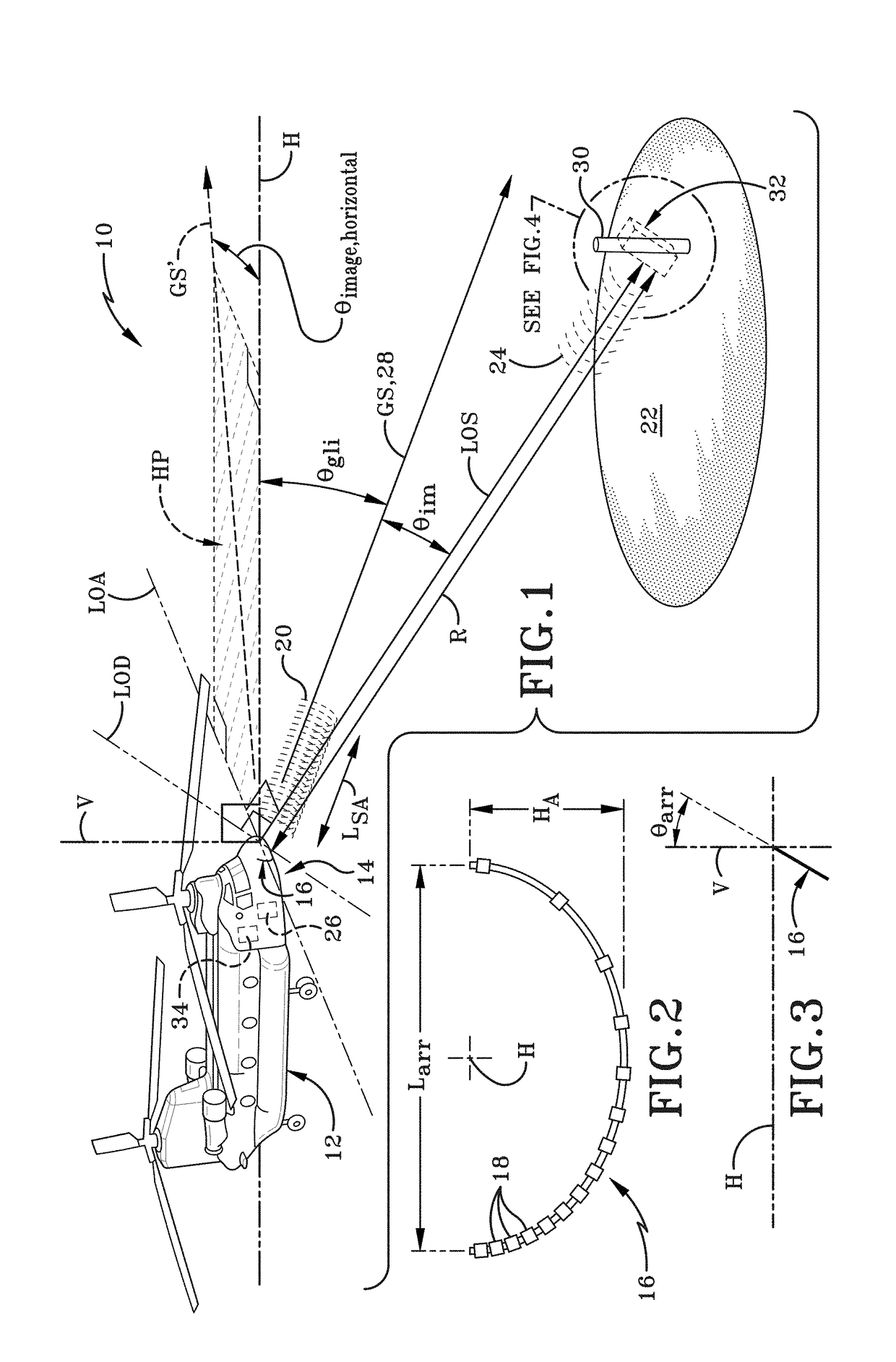
[0019]In accordance with one aspect of the present disclosure, a system and method for generating high-resolution three-dimensional imagery using electromagnetic signals is provided. As depicted in FIG. 1, the imaging system is broadly depicted as 10. Imaging system 10 may include a moveable vehicle 12 and a multiple-input multiple-output (MIMO) radar system 14. The MIMO radar system 14 may include an antenna array 16 having a plurality of antenna elements 18 carried by the vehicle 12. One or more of the antenna elements 18 may transmit electromagnetic signals 20 toward a target area 22 spaced apart from the antenna elements 18 and one or more of the antenna elements 18 may receive back-scattered electromagnetic signals 24 reflected from the target area 22. The imaging system 10 may further include at least one non-transitory computer readable storage medium 26.

[0020]FIG. 1 depicts vehicle 12 as a rotorcraft, however, it is to be entirely understood that vehicle 12 is not intended t...


PUM


Abstract

A system and method for generating high-resolution imagery using electromagnetic signals includes a moveable vehicle and a multiple-input multiple-output (MIMO) radar system carried by the vehicle. The MIMO radar system includes an antenna array having a plurality of antenna elements. One or more of the antenna elements transmits electromagnetic signals towards a target area and one or more of the antenna elements receives back-scattered electromagnetic signals reflected from the target area. The system generates high-resolution three-dimensional imagery based on back-scattered electromagnetic signal data with system performance characterized by: (a) down range resolution ΔR; (b) cross-range resolution ΔX; and (c) vertical resolution ΔH. The system exploits effective synthetic apertures to improve cross-range resolution ΔX and vertical resolution ΔH based on, at least in part, the movement of the vehicle along the trajectory and a width and height of the antenna array relative to the target area.

Description

BACKGROUNDTechnical Field[0001]The present disclosure relates generally to radar systems. More particularly, the present disclosure relates to utilizing a radar system to generate high-resolution imagery. Specifically, the present disclosure relates to utilizing a multiple-input multiple output (MIMO) radar system to generate high-resolution three-dimensional imagery.Background Information[0002]Tactical remote sensing scenarios, such as rotorcraft landing, may become problematic when operating in a degraded visual environment (DVE) caused by, among other things, dust, fog and other fine-grained optical impediments. Examples of DVEs include ‘brownouts’ or ‘whiteouts’ caused by the rotation of the rotorcraft rotor blades in dusty, sandy or snowy areas. As the rotorcraft encounters the DVE, the operator of the rotorcraft may lose visual situational awareness and undergo spatial disorientation which may cause accidents and / or otherwise impede the operator from safely landing the rotorcr...

Claims


Application Information

Patent Timeline
IPC IPC(8): G01S13/90G01S7/20
CPCG01S7/20G01S13/90
Inventor WEICHMAN, PETER B.EKHAUS, IRA
Owner BAE SYST INFORMATION & ELECTRONICS SYST INTERGRATION INC
Why Eureka
Try Eureka