Electric motor

a technology of electric motors and motors, applied in the direction of dynamo-electric machines, electrical apparatus, magnetic circuits, etc., can solve the problems of reducing the efficiency and performance of the motor, reducing the size of the statator core, and heavy manufacturing costs, so as to reduce the cost of the motor, reduce the diameter of the motor, and save spa

Active Publication Date: 2018-12-20
DYSON TECH LTD
View PDF0 Cites 3 Cited by
  • Summary
  • Abstract
  • Description
  • Claims
  • Application Information

AI Technical Summary

Benefits of technology

[0006]As a result, the support body acts as a cartridge containing the rotor assembly, and into which the individual stator elements of the stator assembly can be slotted. This allows the stator assembly to be made smaller, removing their need to take on a structural role within the motor, whilst at the same time maintaining a high level of control over the relative positioning of the rotor and stator assemblies. This cartridge-like package therefore enables the rotor and stator assemblies to be made smaller and lighter, and as such the overall size and weight of the motor can be minimised. What is more, the stator assembly can be manufactured as a number of stator elements, which are then slotted into the support body. This makes the manufacture of the motor far easier, particularly when the cartridge-like package allows for the stator assembly to be made smaller.
[0016]Each of the stator elements may be fixed to the at least one reinforcing member. Accordingly, the stator elements are fixed to the part of the support body that provides the greatest structural support, and any movement of the stator elements during operation of the motor, which could reduce the efficiency of the motor, is minimised.

Problems solved by technology

This can result in stator cores that are bulky, heavy and expensive to manufacture.
This can reduce the efficiency and performance of the motor.

Method used


Image

  • Electric motor
  • Electric motor
  • Electric motor

Examples


Embodiment Construction

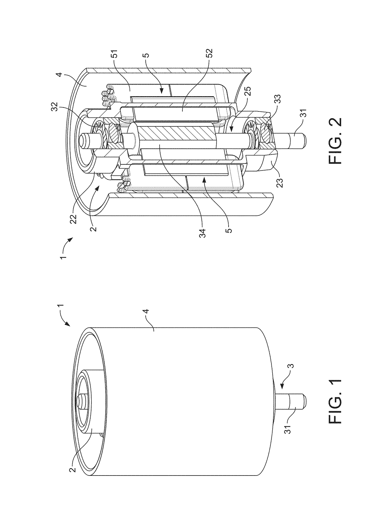
[0027]The electric motor 1 of FIGS. 1 and 2 comprises a stator assembly, a rotor assembly 3, and a support body 2. An outer casing 4 surrounds the stator assembly, rotor assembly 3 and support body 2.

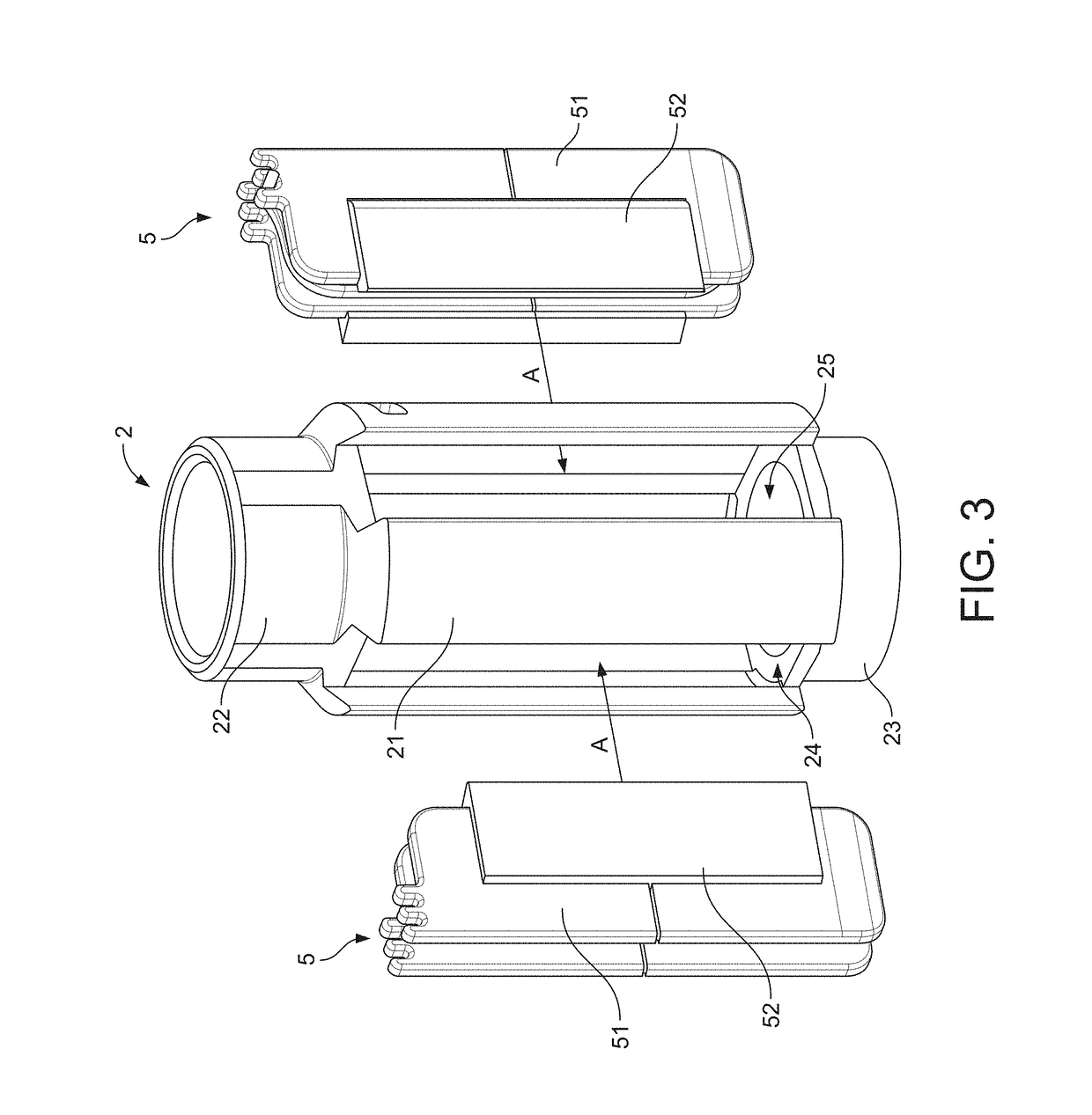
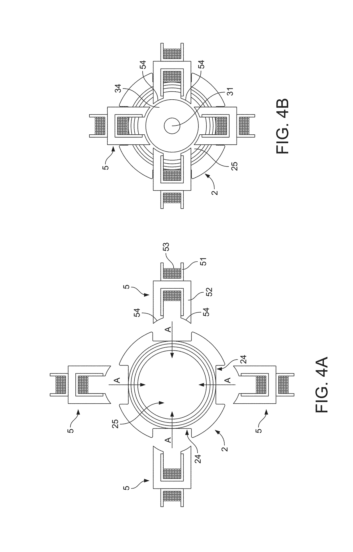
[0028]The stator assembly comprises four stator elements 5, each stator element 5 comprising a c-shaped stator core 52 and a bobbin 51 fixed to the c-shaped stator core 52. Each of the stator elements 5 are fixed to the support body 2, the details of which will be described in more detail below.

[0029]The rotor assembly 3 comprises a shaft 31, bearings 32 and 33, and a magnet 34. The bearings 32, 33 are mounted at either end of the magnet 34. The magnet 34 is a permanent magnet of the sort typically used in brushless permanent magnet motors.

[0030]The support body 2, which can be seen more clearly in FIG. 3, is cylindrical in shape and comprises an elongate central part 21, and first and second bearing seats 22, 23 positioned axially at each end of the elongate central part 21. The elonga...


PUM


Abstract

An electric motor comprising: a stator assembly; a rotor assembly; and a support body. The stator assembly comprises a plurality of stator elements, and the rotor assembly comprises a shaft to which is mounted at least a first and a second bearing mounted either side of a permanent magnet. The support body comprises an elongate central part, and first and second bearing seats positioned axially at opposite ends of the elongated central part to each other, and the elongate central part defines a plurality of openings each configured to receive one of the plurality of stator elements.

Description

REFERENCE TO RELATED APPLICATIONS[0001]This application claims the priority of United Kingdom Application No. 1709831.0, filed Jun. 20, 2017, the entire contents of which are incorporated herein by reference.FIELD OF THE INVENTION[0002]The present invention relates to an electric motor.BACKGROUND OF THE INVENTION[0003]Electric motors typically comprise a rotor assembly, a stator assembly and a frame which holds the components together. The stator assembly is typically mounted to the frame using the iron stator core. This allows the positioning of the stator core relative to other components of the motor, such as the rotor assembly, to be carefully controlled. However, using the stator cores in a structural role to achieve accurate positioning of the motor's components requires the stator cores to be made very robust and to a very high tolerance. This can result in stator cores that are bulky, heavy and expensive to manufacture. In addition, the requirement for such stator cores to i...

Claims


Application Information

Patent Timeline
Patent Type & Authority Applications(United States)
IPC IPC(8): H02K1/17H02K1/14H02K1/20F04D25/08
CPCH02K1/17H02K1/141H02K1/20F04D25/082H02K1/185H02K1/28H02K5/161H02K5/128H02K5/1732H02K7/083H02K7/14H02K2213/03H02K5/20H02K5/04
Inventor CLOTHIER, ANDREW CHARLTONKING, GARY FRANCIS
Owner DYSON TECH LTD
Why Eureka
Try Eureka