
Non-spherical cavity electrophoretic displays and materials for making the same

a technology of electrophoretic display and non-spherical cavity, which is applied in the field of encapsulated electrophoretic display, can solve the problems of preventing their widespread use and overcoming inadequate lifetimes of display, and achieves the effects of disorienting anisotropic particles, improving the optical properties of the system, and improving the control of absorbance and density

Inactive Publication Date: 2006-11-02
E INK CORPORATION
View PDF99 Cites 17 Cited by
  • Summary
  • Abstract
  • Description
  • Claims
  • Application Information

AI Technical Summary

Benefits of technology

[0063] The advantage of this system is that known emulsification or encapsulation techniques can be used to make improved particles, with better control of absorbance, optical properties, charge, mobility, shape, size, density, surface chemistry, stability, and processibility. There are vast numbers of dyes and / or particles and liquids of all polarities that can be used to gain a high level of control over the optical properties of the system. It is possible to create particles which are capsules containing dyes and / or particles in order to obtain properties difficult to achieve with pigments. The present invention relates to these encapsulated electrophoretic displays and the materials, such as dyes, pigments, binder, etc. that may be useful in their construction.
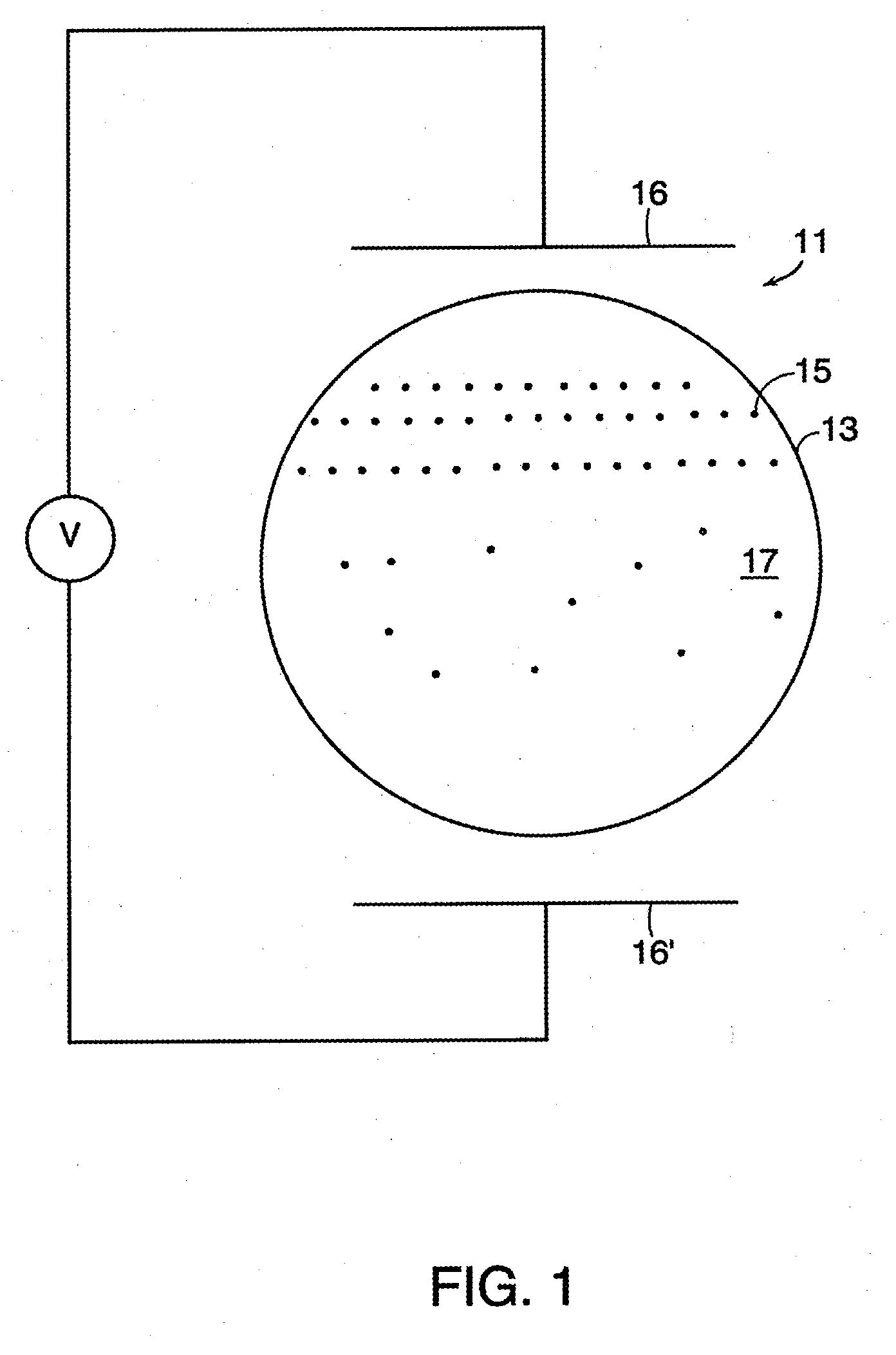
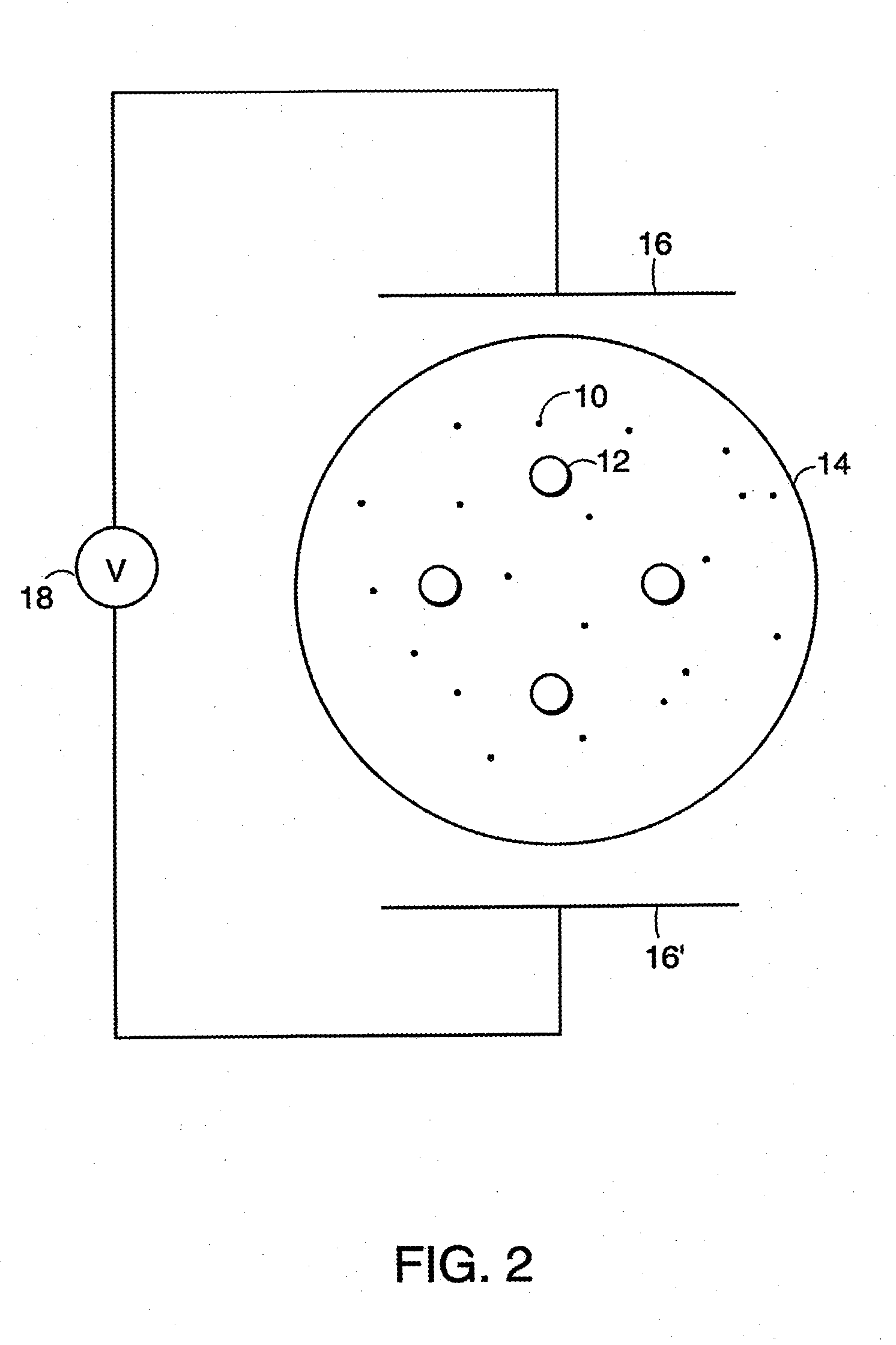
[0064] Encapsulated electrophoretic displays may include two or more different types of particles. Such displays may include, for example, displays containing a plurality of anisotropic particles and a plurality of second particles in a suspending fluid. Application of a first electric field may cause the anisotropic particles to assume a specific orientation and present an optical property. Application of a second electric field may then cause the plurality of second particles to translate, thereby disorienting the anisotropic particles and disturbing the optical property. Alternatively, the orientation of the anisotropic particles may allow easier translation of the plurality of second particles. The particles may have a refractive index that substantially matches the refractive index of the suspending fluid.

Problems solved by technology

Nevertheless, problems with the long-term image quality of these displays has, to date, prevented their widespread usage.
The clustering and settling problems, which plagued prior art electrophoretic displays and resulted in inadequate lifetimes for the displays are now overcome.

Method used


Image

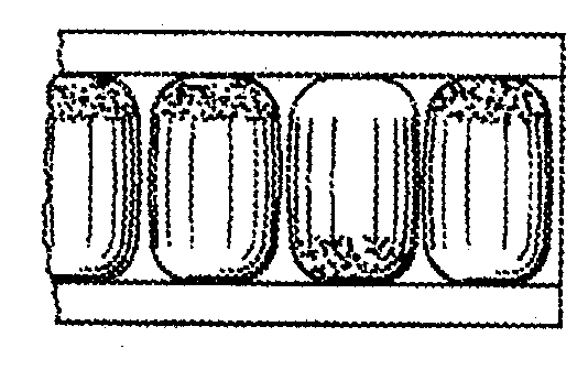
  • Non-spherical cavity electrophoretic displays and materials for making the same
  • Non-spherical cavity electrophoretic displays and materials for making the same
  • Non-spherical cavity electrophoretic displays and materials for making the same

Examples


example 1

[0192] The following procedure describes gelatin / acacia microencapsulation for use in electrophoretic displays of the present invention.

[0193] A. Preparation of Oil (Internal) Phase

[0194] To a 1 L flask is added 0.5 g of Oil Blue N (Aldrich, Milwaukee, Wis.), 0.5 g of Sudan Red 7B (Aldrich), 417.25 g of Halogenated hydrocarbon Oil 0.8 (Halogenated hydrocarbon Products Corp., River Edge, N.J.), and 73.67 g of Isopar-G® (Exxon, Houston, Tex.). The mixture is stirred at 60° C. for six hours and is then cooled to room temperature. 50.13 g of the resulting solution is placed in a 50 mL polypropylene centrifuge tube, to which is added 1.8 g of titanium dioxide (TiO2) (E.I. du Pont de Nemours and Company, Wilmington, Del.), 0.78 g of a 10% solution of OLOA 1200 (Chevron, Somerset, N.J.), in Halogenated hydrocarbon Oil 0.8, and 0.15 g of Span 85 (Aldrich). This mixture is then sonicated for five minutes at power 9 in an Aquasonic Model 75D sonicator (VWR, Westchester, Pa.) at 30° C.

[0195...

example 2

[0205] The following is an example of the preparation of microcapsules by in situ polymerization.

[0206] In a 500 mL non-baffled jacketed reactor is mixed 50 mL of a 10 wt % aqueous solution of ethylene co-maleic anhydride (Aldrich), 100 mL water, 0.5 g resorcinol (Aldrich), and 5.0 g urea (Aldrich). The mixture is stirred at 200 rpm and the pH adjusted to 3.5 with a 25 wt % NaOH solution over a period of 1 minute. The pH is monitored using a pH meter that was previously calibrated with pH 7.0 and pH 4.0 buffer solutions. To this is slowly added the oil phase, prepared as described above in Ex. 1, and agitation is increased to 450 rpm to reduce the average particle size to less than 200 μm. 12.5 g of a 37 wt % aqueous formaldehyde solution is then added and the temperature raised to 55° C. The solution is heated at 55° C. for two hours.

example 3

[0207] The following is an example of the preparation of microcapsules by interfacial polymerization.

[0208] To 44 g of the oil phase, prepared as described above in Ex. 1, is added 1.0 g of sebacoyl chloride (Aldrich). Three milliliters of the mixture is then dispersed in 200 mL of water with stirring at 300 rpm at room temperature. To this dispersion is then added 2.5 mL of a 10 wt. % aqueous solution of 1,6-diaminohexane. Capsules form after about one hour.


PUM

PropertyMeasurementUnit
aspect ratioaaaaaaaaaa

Abstract

Disclosed herein are novel electrophoretic displays and materials useful in fabricating such displays. In particular, novel encapsulated displays are disclosed. Particles encapsulated therein are dispersed within a suspending, or electrophoretic, fluid. This fluid may be a mixture of two or more fluids or may be a single fluid. The displays may further comprise particles dispersed in a suspending fluid, wherein the particles contain a liquid. In either case, the suspending fluid may have a density or refractive index substantially matched to that of the particles dispersed therein. Finally, also disclosed herein are electro-osmotic displays. These displays comprise at least one capsule containing either a cellulosic or gel-like internal phase and a liquid phase, or containing two or more immiscible fluids. Application of electric fields to any of the electrophoretic displays described herein affects an optical property of the display.

Description

CROSS-REFERENCE TO RELATED APPLICATIONS [0001] The present application is a continuation of U.S. Ser. No. 10 / 329,023, filed Dec. 23, 2002 (Publication No. 2003 / 0112491). [0002] U.S. Ser. No. 10 / 329,023 is a continuation of U.S. Ser. No. 09 / 140,846, filed Aug. 27, 1998 (now U.S. Pat. No. 6,727,881). [0003] U.S. Ser. No. 09 / 140,846 is, in turn, a continuation-in-part of each of three earlier applications, namely: [0004] (a) U.S. Ser. No. 08 / 504,896, filed Jul. 20, 1995 (now U.S. Pat. No. 6,124,851); [0005] (b) U.S. Ser. No. 08 / 983,404 filed Mar. 26, 1999; and [0006] (c) U.S. Ser. No. 08 / 935,800, filed Sep. 23, 1997 (now U.S. Pat. No. 6,120,588). [0007] U.S. Ser. No. 09 / 140,846 also claims benefit of each of the following applications: [0008] (1) U.S. Ser. No. 60 / 057,133, filed Aug. 28, 1997; [0009] (2) U.S. Ser. No. 60 / 057,716, filed Aug. 28, 1997; [0010] (3) U.S. Ser. No. 60 / 057,799, filed Aug. 28, 1997; [0011] (4) U.S. Ser. No. 60 / 057,163, filed Aug. 28, 1997; [0012] (5) U.S. Ser. N...

Claims


Application Information

Patent Timeline
Patent Type & Authority Applications(United States)
IPC IPC(8): G02B26/00B25B13/46B25G3/30B41J3/407G02B26/02G02F1/00G02F1/133G02F1/1333G02F1/1334G02F1/1343G02F1/1345G02F1/135G02F1/1365G02F1/167G02F1/16757G04G21/04G06F3/14G06F3/147G06F15/02G09F9/302G09F9/37H01L27/12H01L27/28H01L51/00H01L51/05H01L51/30
CPCB25B13/461G02B26/005B82Y10/00G02B26/026G02F1/133305G02F1/133348G02F1/13336G02F1/1334G02F1/1343G02F1/1345G02F1/135G02F1/1365G02F1/167G02F1/172G02F2001/1672G02F2001/1678G02F2202/12G02F2202/28G06F15/0283G06K19/07703G09F9/302G09F9/372H01L27/12H01L27/28H01L51/0036H01L51/0038H01L51/0045H01L51/005H01L51/0051H01L51/0052H01L51/0077H01L51/0078H01L51/0508H01L51/0512B41J3/4076G02F1/1681G02F1/16757H10K85/113H10K85/114H10K85/20H10K85/611H10K85/60H10K85/615H10K85/311H10K85/30H10K10/46H10K10/462H10K19/00
Inventor ALBERT, JONATHAN D.COMISKEY, BARRETTJACOBSON, JOSEPH M.ZHANG, LIBINGLOXLEY, ANDREWFEENEY, ROBERTDRZAIC, PAULMORRISON, IAN
Owner E INK CORPORATION
Learn More