Fuel tank inerting system

a fuel tank and inerting technology, which is applied in fire rescue, aircraft components, air-treatment apparatus arrangements, etc., can solve the problems of electrical sparks in the ullage volume of the tank, catastrophic explosion, and fire/explosion risk of flammable ullage in aircraft fuel tanks

Active Publication Date: 2018-12-27
AIRBUS OPERATIONS LTD
View PDF0 Cites 3 Cited by
  • Summary
  • Abstract
  • Description
  • Claims
  • Application Information

AI Technical Summary

Benefits of technology

[0030]One or more said modules may be located within or adjacent one or more said fuel tanks for direct access to a said ullage volume. The modules may be of very diminutive size, for example contained in a box 50 cm by 30 cm by 30 cm or less where a catalytic system is used. They may therefore be located adjacent to, or even within, the fuel tanks. Thus, they may conveniently be mounted on a wing spar or within a dry bay mounted near to or on a fuel tank wall. Extensive pipework may therefore be avoided which would otherwise be necessary to connect inerting systems located remotely, for example in the aircraft fuselage, to wing fuel tanks which may extend as far away as wing extremities.
[0031]The inerting system may include means such as fans to circulate the ullage gas within the one or more fuel tanks. Such fans or other means are conveniently comprised in the modules and may assist complete inerting of the ullage volume. For small modules or modules whose size places few restrictions upon their placement on the aircraft, placement of modules in locations where natural movement of fuel and gasses within the fuel system may ensure sufficient fuel tank inerting without the use of fans or other means to move the gasses through some or all of the modules. Any natural convection of ullage within the fuel system may therefore be taken advantage of.

Problems solved by technology

Highly flammable ullage comprising air and fuel vapour can form above fuel stored in aircraft fuel tanks and certain conditions such as a low fuel level in the tank and rising temperatures can create conditions which, with a single spark, can ignite the fuel and lead to a catastrophic explosion.
Flammable ullage in aircraft fuel tanks is also a fire / explosion risk in a lightning strike on the aircraft.
Electrical sparks in the ullage volume of the tank, caused by the strike, can be catastrophic unless the ullage is inerted.
For military aircraft, the risk of fire or explosion of the fuel tanks is increased by the threat of a breach of the fuel tanks by bullets or missiles from enemy action.

Method used


Image

  • Fuel tank inerting system
  • Fuel tank inerting system
  • Fuel tank inerting system

Examples


Embodiment Construction

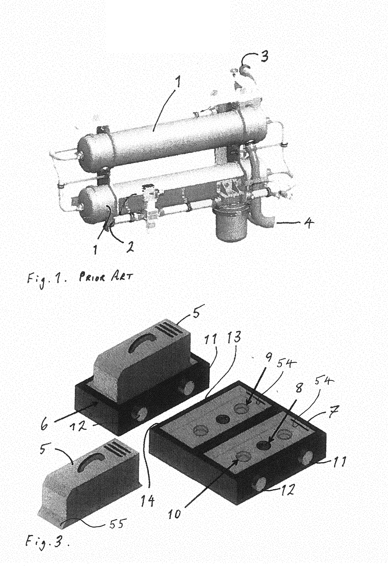
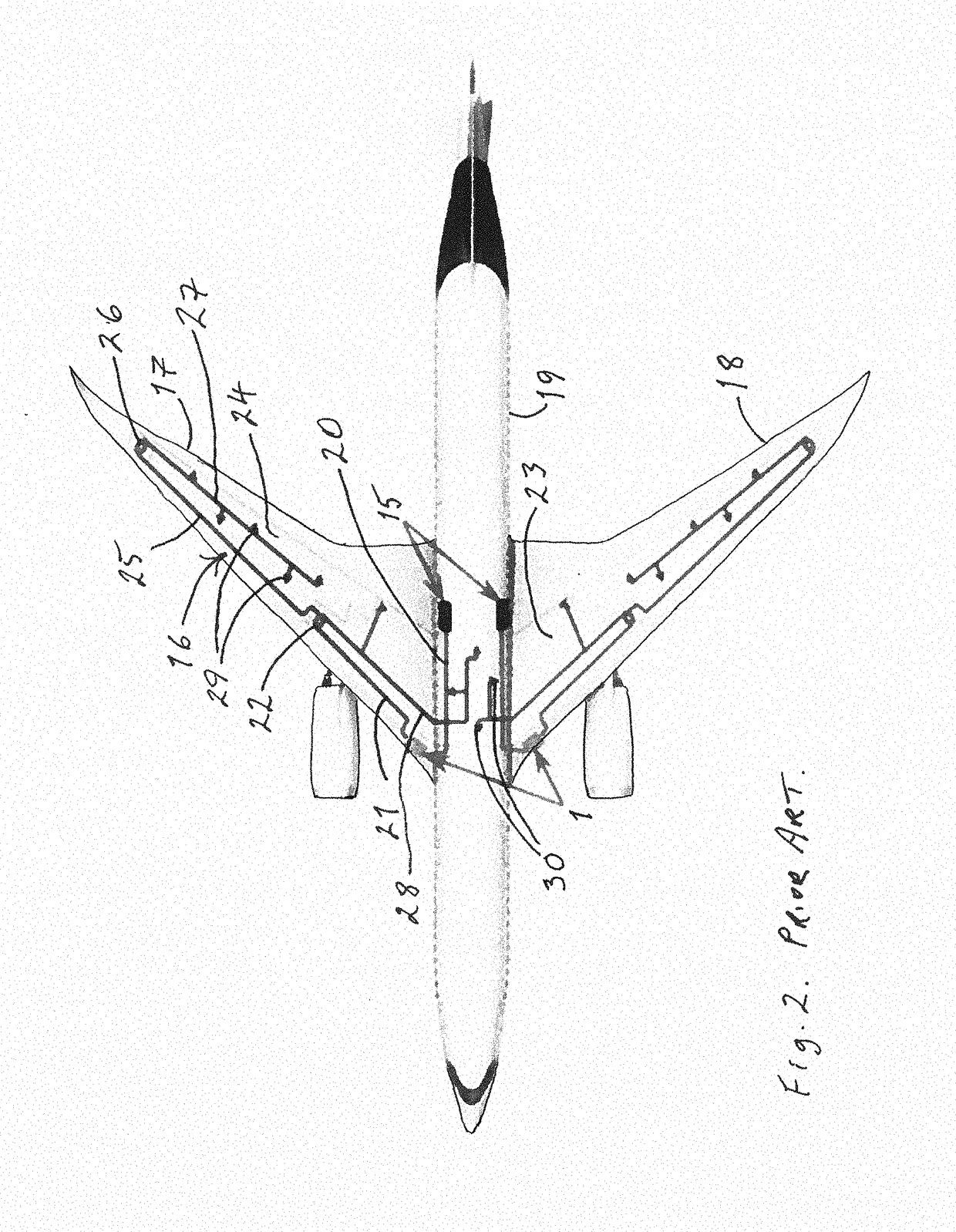
[0044]With reference to FIG. 1, there is shown a prior art arrangement, as used for inerting fuel tank ullage in an aircraft. The arrangement comprises two ASMs 1 linked to various pipework. In particular, an air inlet 2 is shown, together with an NEA outlet 3 and an oxygen enriched air (OEA) outlet 4. The air inlet will normally be from a CSAS, receiving air from an engine bleed on the aircraft. The NEA outlet 3 is connected to one or more fuel tanks (see FIG. 3) to replace the fuel vapour-filled ullage. The OEA outlet 4 is vented overboard.

[0045]As can be seen from FIG. 1, the current inerting arrangement is not designed for close packaging or easy installation. It is one metre or more in length, approximately the same height or slightly less and is clearly susceptible to accidental damage, with all the constituent parts being quite exposed. In current Airbus aircraft, the arrangement is mounted underneath the fuselage of the aircraft in the air conditioning pack area, within the ...


PUM


Abstract

A fuel tank inerting module, a fuel tank inerting system for an aircraft, and a method of providing fuel tank inerting systems for aircraft are disclosed. The module includes an inlet for ullage gas from a fuel tank, a catalyst, an outlet for the ODA, sensors, filters and valves. The module is sized and shaped to fit in a range of positions near to fuel tanks in various aircraft. The inerting system includes one or more modules connected to the fuel tanks and a controller to control passage of ullage and ODA between the fuel tanks and the modules. The method includes providing an inert gas generation module compatible with any suitable aircraft, positioning one or more modules in an aircraft at locations near to a fuel tank to be inerted.

Description

FIELD OF TECHNOLOGY[0001]The present invention relates to a system for inerting fuel vapour mixed with air in a fuel tank and more particularly to a system for inerting fuel vapour and air in an aircraft fuel tank.BACKGROUND[0002]It is well known to provide fuel tank inerting systems for aircraft, in particular for commercial aircraft. Ullage in a fuel tank comprises the gaseous content of the tank above the fuel. Highly flammable ullage comprising air and fuel vapour can form above fuel stored in aircraft fuel tanks and certain conditions such as a low fuel level in the tank and rising temperatures can create conditions which, with a single spark, can ignite the fuel and lead to a catastrophic explosion. Flammable ullage in aircraft fuel tanks is also a fire / explosion risk in a lightning strike on the aircraft. Electrical sparks in the ullage volume of the tank, caused by the strike, can be catastrophic unless the ullage is inerted.[0003]For military aircraft, the risk of fire or e...

Claims


Application Information

Patent Timeline
Patent Type & Authority Applications(United States)
IPC IPC(8): B64D37/32B64D13/06A62C3/06A62C3/08
CPCB64D37/32B64D13/06A62C3/065A62C3/08B64D2013/0618A62C99/0018
Inventor FROST, NEIL TERENCEPLASTOW, IAN
Owner AIRBUS OPERATIONS LTD
Why Eureka
Try Eureka