Gasification system and process

a technology of gasification system and process, applied in the direction of horizontal gasifiers, gasifier mechanical details, combustible gas production, etc., can solve the problems of reducing the cooling function reducing the ability of the quench ring to perform the cooling function, etc., to achieve severe corrosion

Active Publication Date: 2018-12-27
AIR PROD & CHEM INC
View PDF3 Cites 0 Cited by
  • Summary
  • Abstract
  • Description
  • Claims
  • Application Information

AI Technical Summary

Benefits of technology

[0026]In addition, the material of the dip tube is protected with a water film on the inner surface of the dip tupe, which prevents the buildup of deposits and cools the

Problems solved by technology

The prior art quench ring thus is vulnerable to thermal damage and thermal chemical degradation.
Furthermore any slag accumulation on the quench ring will reduce the ability of the quench ring to perform its cooling function.
The equilibrium radius is occasionally far enough from the center axis of the gasifier and the leading edge of the floor such that there is a risk that the floor can no longer sustain the overlying refractory.
If refractory support is in jeopardy, the gasifier may require premature shut down for reconstructive work on the floor and replacement of the throat refractory, a very time intensive and laborious procedure.
Another problem at the intermediate section or throat section of the prior art gasifier is that the upper, curved surface of the quench ring is exposed to full radiant heat from the reaction chamber of the gasifier, and the corrosive and/or erosive effects of the high velocity, high temperature syngas which can include ash and slag.
Such harsh conditions can also lead to wastage problems of the quench ring which, if severe enough, can force termination of gasification operations for necessary repair work.
This problem is exacerbated if the overlying floor has wasted away significantly, exposing more of the quench ring to the hot gas and slag.
It was reported that the above described design had experienced frequent failures such as wearing off and corrosion of the refractory bricks, metal floor and the quench ring

Method used


Image

  • Gasification system and process
  • Gasification system and process
  • Gasification system and process

Examples


Embodiment Construction

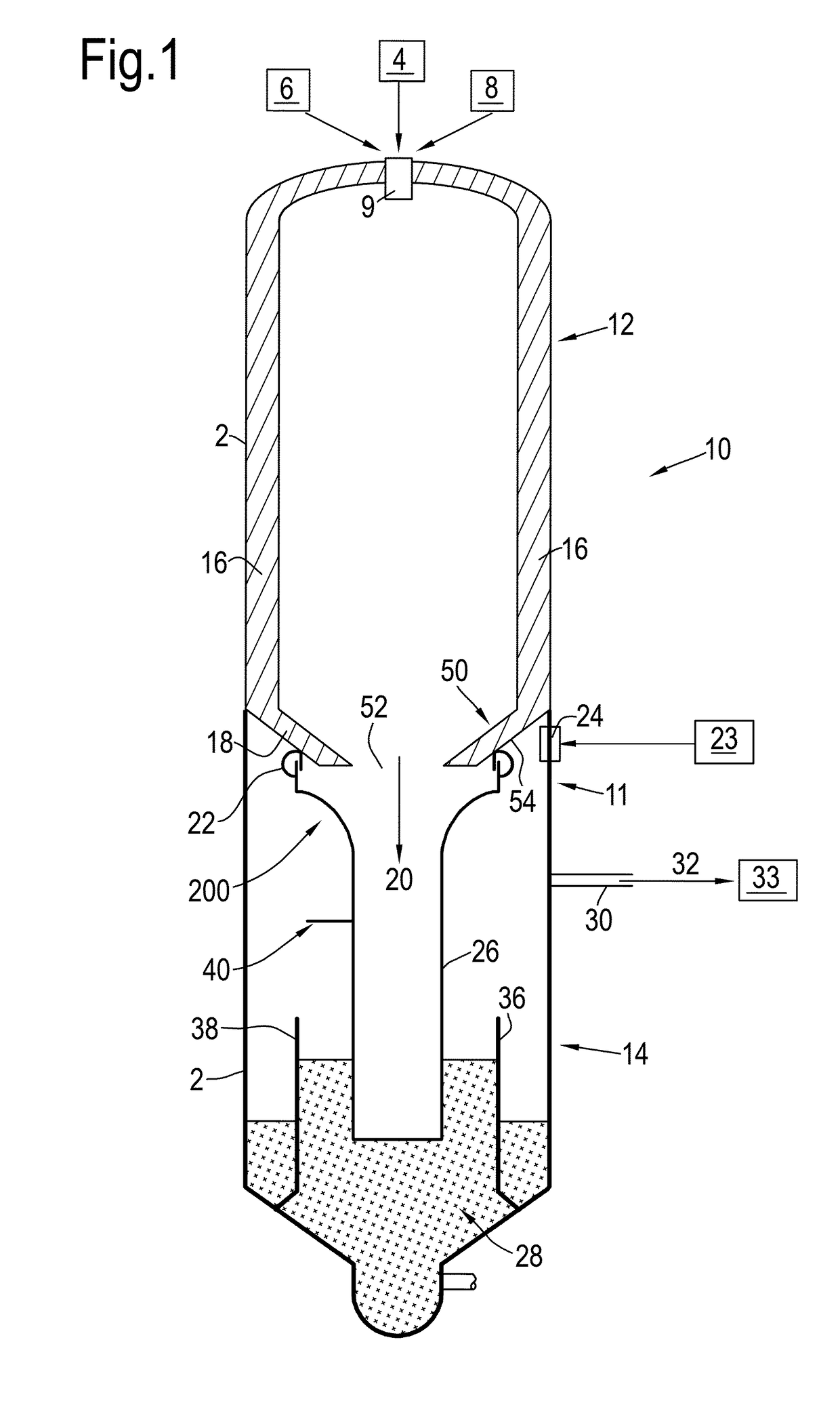
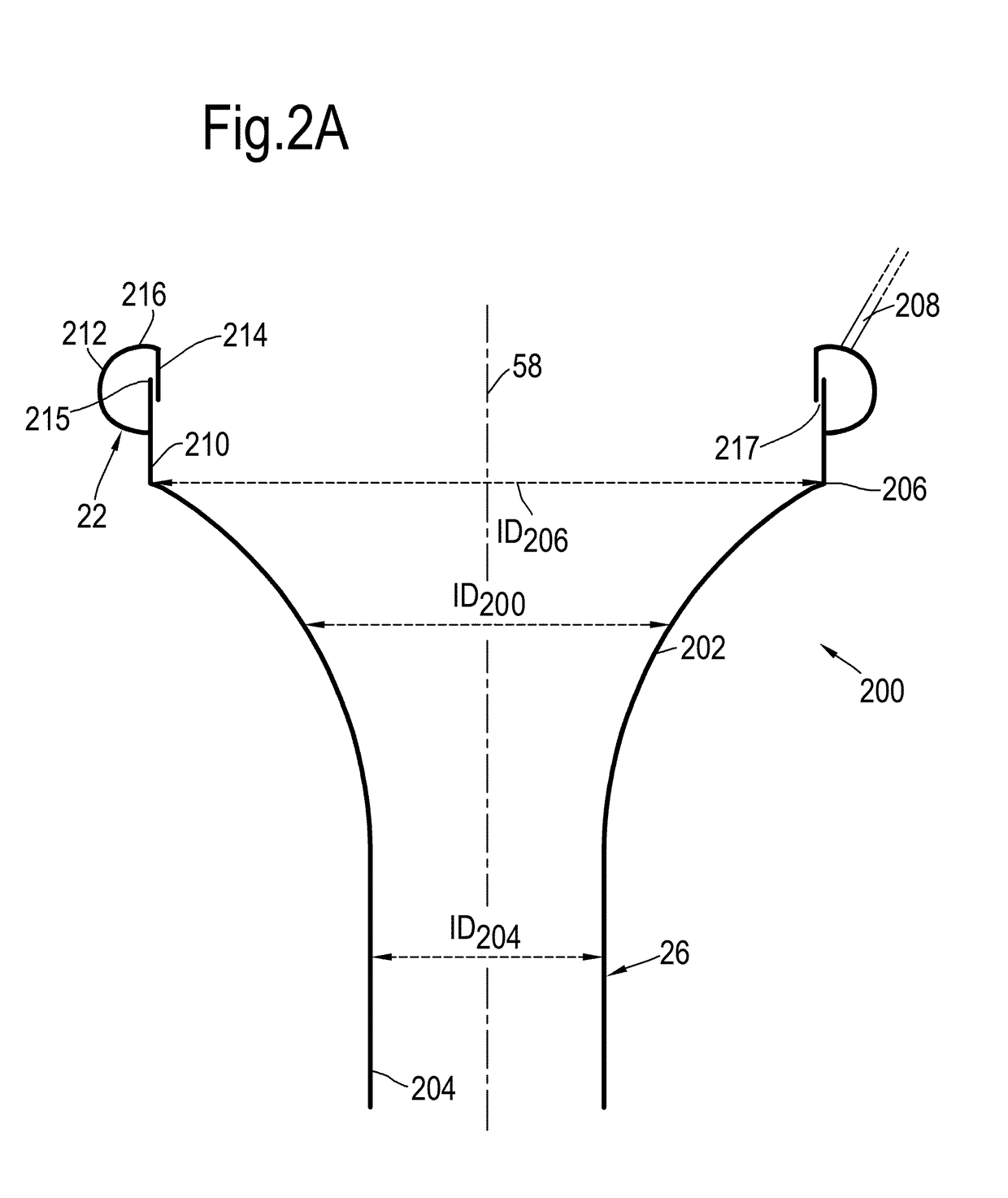
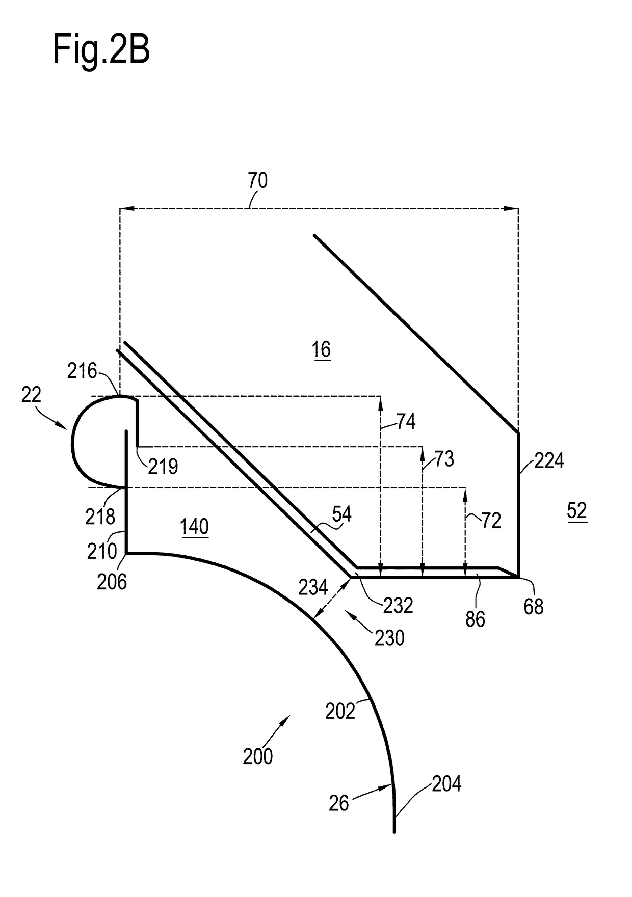
[0049]The disclosed embodiments, discussed in detail below, are suitable for gasifier systems that include a reaction chamber that is configured to convert a feedstock into a synthetic gas, a quench chamber that is configured to cool the synthetic gas, and a quench ring that is configured to provide a water flow to the quench chamber. The synthetic gas passing from the reaction chamber to the quench chamber may be at a high temperature. Thus, in certain embodiments, the gasifier includes embodiments of an intermediate section, between the reactor and the quench chamber, that is configured to protect the quench ring or metal parts from the synthetic gas and / or molten slag that may be produced in the reaction chamber. The synthetic gas and molten slag may collectively be referred to as hot products of gasification. A gasification method may include gasifying a feedstock in the reaction chamber to generate the synthetic gas, and quenching the synthetic gas in the quench chamber to cool...


PUM


Abstract

A gasification system for the partial oxidation of a carbonaceous feedstock to at least provide a synthesis gas, comprising: a reactor chamber for receiving and partially oxidizing the carbonaceous feedstock, the reactor chamber having a reactor chamber floor; a quench chamber below the floor of the reactor chamber for holding a bath of liquid coolant; an intermediate section at said reactor chamber floor, the intermediate section having a reactor outlet opening through which the reactor chamber communicates with the quench chamber to conduct the synthesis gas from the reactor chamber into the bath of the quench chamber; at least one layer of refractory bricks arranged on and supported by the reactor chamber floor, the lower end section of the refractory bricks enclosing the reactor outlet opening and defining the inner diameter thereof; and a dip tube extending from the reactor outlet opening to the bath of the quench chamber, the dip tube having a widened top section.

Description

BACKGROUND OF THE INVENTION[0001]The invention relates to a gasification system and a process for the production of synthesis gas by partial combustion of a carbonaceous feed.[0002]The carbonaceous feed can for instance comprise pulverized coal, biomass, (heavy) oil, crude oil residue, bio-oil, hydrocarbon gas or any other type of carbonaceous feed or mixture thereof.[0003]Syngas, or synthesis gas, as used herein is a gas mixture comprising hydrogen, carbon monoxide, and potentially some carbon dioxide. The syngas can be used, for instance, as a fuel, or as an intermediary in creating synthetic natural gas (SNG) and for producing ammonia, methanol, hydrogen, waxes, synthetic hydrocarbon fuels or oil products, or as a feedstock for other chemical processes.[0004]The disclosure is directed to a system comprising a gasification reactor for preparing syngas, and a quench chamber for receiving the syngas from the reactor. A syngas outlet of the reactor is fluidly connected with the quenc...

Claims


Application Information

Patent Timeline
IPC IPC(8): C10J3/84C10J3/74C10J3/78C10J3/00
CPCC10J3/845C10J3/74C10J3/78C10J3/002C10J2200/09C10J2300/1846
Inventor SCHMITZ-GOEB, MANFRED HEINRICHKARZEL, PAUL CHRISTIAN
Owner AIR PROD & CHEM INC
Why Eureka
Try Eureka