
Road rail stoneblower

a road rail and stoneblower technology, applied in the field of road rail stoneblowers, can solve the problems of voids or gaps under rail ties, stoneblowers have some drawbacks, and the traditional method of fixing voids that appeared under rail ties was labor and time-consuming, so as to improve the alignment of railroad tracks

Active Publication Date: 2018-12-27
HARSCO TECH
View PDF0 Cites 3 Cited by
  • Summary
  • Abstract
  • Description
  • Claims
  • Application Information

AI Technical Summary

Benefits of technology

The patent describes an improved system for maintaining track alignment on railways. The system uses a vehicle that can operate on both road surfaces and railways to dispense ballast stones onto the track. This raises the track level, improving alignment and stability. The system allows for efficient and effective maintenance of railways.

Problems solved by technology

Over time, normal wear and tear on the railroad may cause the rails to deviate from a desired profile based on movement of the underlying ballast, and as such voids or gaps under the rail ties may appear.
The traditional method of fixing voids that appeared under rail ties was very labor and time intensive, as it required measurement of the voids under each individual rail tie, manually lifting the rail ties, and then spreading a pre-measured quantity of ballast under the rail ties to raise the rails.
Stoneblowers have some drawbacks, however, based on the current rail-bound design.
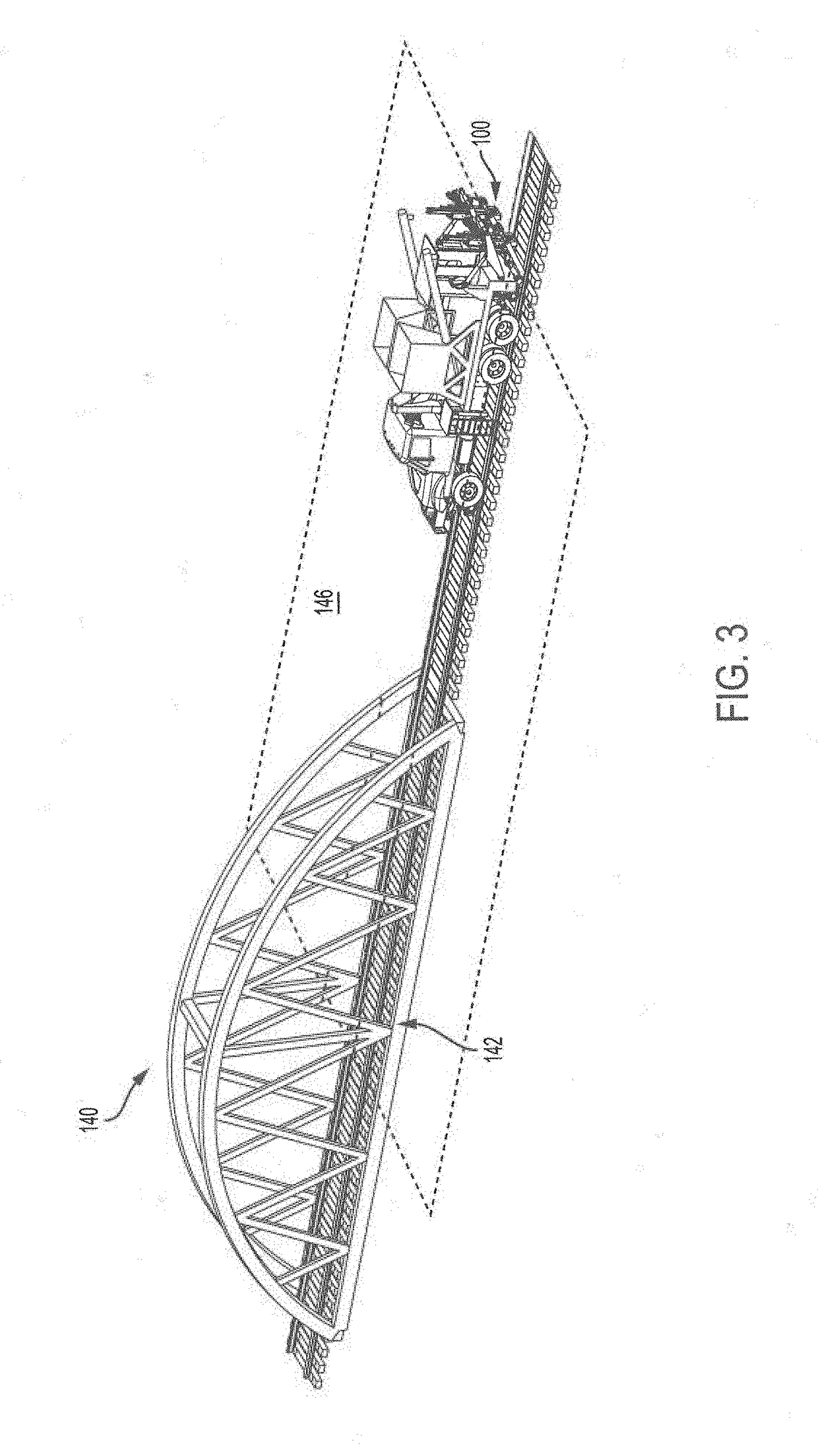
When conventional stoneblowers approach a fixed structure, such as a bridge, such machines are capable of adequately blowing ballast adjacent to the fixed structure in a first direction, but cannot adequately blow ballast adjacent to the fixed structure at the opposite side of the fixed structure due to the positioning of the blowing tubes and jacking mechanism.
This is because the jacking mechanism is unable to lift the fixed structure in order to blow ballast underneath a tie located adjacent to the fixed structure.

Method used


Image

  • Road rail stoneblower
  • Road rail stoneblower
  • Road rail stoneblower

Examples


Embodiment Construction

[0025]Various embodiments of a road rail stoneblower are described according to the present disclosure. It is to be understood, however, that the following explanation is merely exemplary in describing the devices and methods of the present disclosure. Accordingly, several modifications, changes, and substitutions are contemplated.

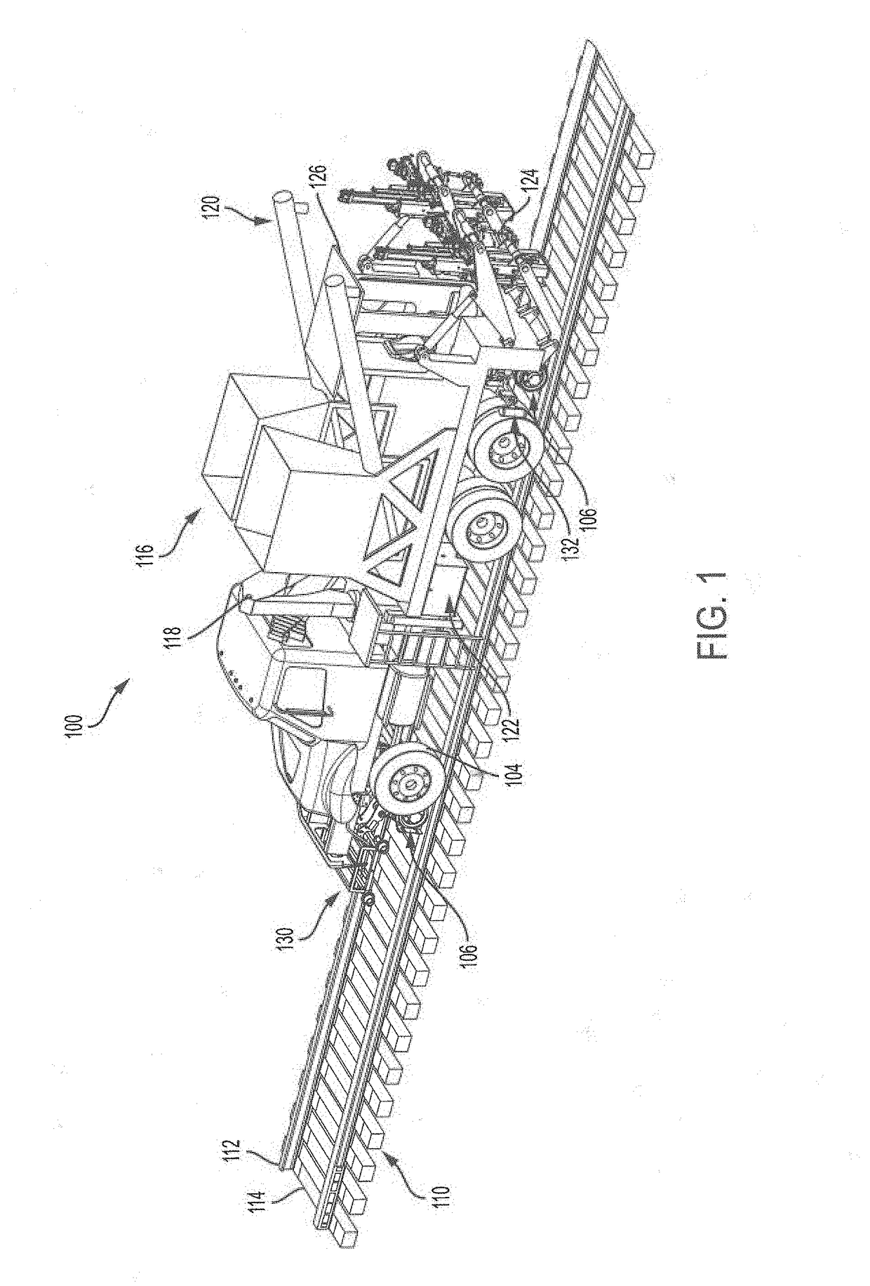
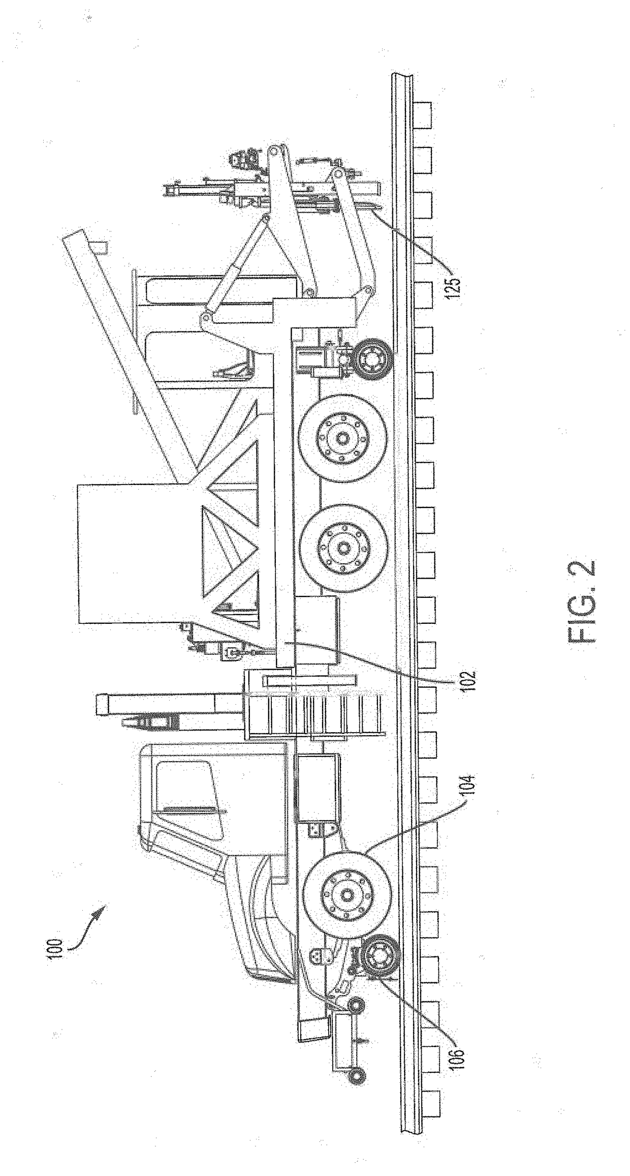
[0026]In an embodiment, and as shown in FIG. 1 and FIG. 2, a road rail stoneblower is depicted having reference numeral 100. The road rail stoneblower 100 may include a chassis 102 configured for operating on both paved or unpaved road surfaces and railroad tracks. For example, the road rail stoneblower 100 may include a first set of wheels 104 configured for traveling on road surfaces as well as a second set of wheels 106 configured for traveling on top of railroad tracks. In this manner, the road rail stoneblower 100 may embody a highway-rail or “hi-rail” vehicle.

[0027]As described throughout, an underlying railroad track 110 may include a pair of elonga...


PUM


Abstract

The present disclosure generally relates to a road rail stoneblower vehicle for carrying out rail maintenance operations near fixed structures such as bridges and overpasses. The road rail stoneblower includes a hi-rail chassis having a first set of wheels configured to engage a road surface and a second set of wheels configured to engage surfaces of substantially parallel rails of a railroad track. The road rail stoneblower further includes a plurality of workheads that are capable of dispensing ballast stones into a bed of ballast underlying the railroad track to adjust the height of the rails. The road rail stoneblower further includes a leveling system detachedly coupled to the hi-rail chassis that is configured to transmit a detectable signal that defines a reference plane with which the rails are to be aligned. Related methods of operation of the road rail stoneblower vehicle and associated maintenance of ballast beds underlying railroad tracks are also described.

Description

CROSS-REFERENCE TO RELATED APPLICATIONS[0001]This application claims priority to U.S. Provisional App. Ser. No. 62 / 523,381 filed on Jun. 22, 2017, which is hereby incorporated by reference in its entirety.BACKGROUND[0002]Railroads are typically constructed to include a pair of elongated, substantially parallel rails, which are coupled to a plurality of laterally extending rail ties. The rail ties are disposed on a ballast bed of hard particulate material such as gravel and are used to support the rails. Over time, normal wear and tear on the railroad may cause the rails to deviate from a desired profile based on movement of the underlying ballast, and as such voids or gaps under the rail ties may appear.[0003]The traditional method of fixing voids that appeared under rail ties was very labor and time intensive, as it required measurement of the voids under each individual rail tie, manually lifting the rail ties, and then spreading a pre-measured quantity of ballast under the rail t...

Claims


Application Information

Patent Timeline
IPC IPC(8): E01B27/02E01B27/18E01B29/04
CPCE01B27/022E01B27/18E01B29/04E01B2203/062E01B2203/08E01B2203/10E01B2203/141E01B2203/16E01B35/00E01B27/17B60F1/043
Inventor HOFER, BRETT
Owner HARSCO TECH
Learn More