A two rotational and one translational degrees of freedom parallel manipulator with high rotational capability

a technology of rotational freedom and parallel manipulator, which is applied in the field of robots, can solve problems such as limiting the application of the mechanism, and achieve the effects of large turning angle, simple structure and large turning angl

Active Publication Date: 2018-12-27
ZHEJIANG SCI-TECH UNIV
View PDF0 Cites 17 Cited by
  • Summary
  • Abstract
  • Description
  • Claims
  • Application Information

AI Technical Summary

Benefits of technology

[0004]The technical problem to be solved by the present disclosure is to provide a two-turn-one-movement parallel mechanism with a large turning angle to overcome the d...

Problems solved by technology

The ball pairs have a relatively small turning scope, so the whole parallel mechanism...

Method used


Image

  • A two rotational and one translational degrees of freedom parallel manipulator with high rotational capability
  • A two rotational and one translational degrees of freedom parallel manipulator with high rotational capability
  • A two rotational and one translational degrees of freedom parallel manipulator with high rotational capability

Examples


embodiment 1

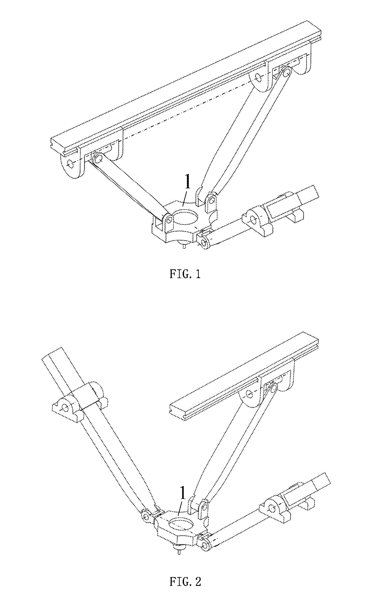
[0031]As shown in FIGS. 1, 6, 7 and 8, a two-turn-one-movement parallel mechanism with a large turning angle includes a machine frame (not shown in the drawings), a movable platform 1, and one first branch and two second branches that are connected between the machine frame and the movable platform in parallel.

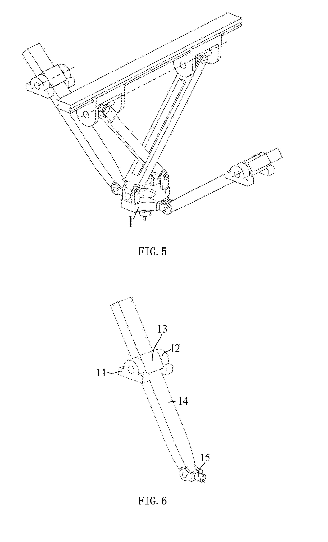
[0032]The first branch includes a first bearing base 11 and a second bearing base 12 (the turning shafts of the two bearing bases are coaxial), a first moving pair slider 13, a first moving pair guide rod 14 and a first universal joint 15 which are connected between the machine frame and the movable platform in turn, wherein the first bearing base and the second bearing base are installed on the machine frame, a rotating shaft 16 on the first moving pair slider is matched with the first bearing base and the second bearing base to form a machine frame turning pair, the first moving pair slider is matched with the first moving pair guide rod to form a first moving pair, and the ...

embodiment 2

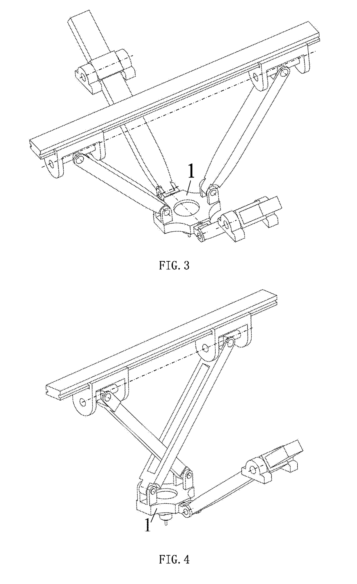
[0036]As shown inFIGS. 2, 6, 7 and 8, a two-turn-one-movement parallel mechanism with a large turning angle includes a machine frame (not shown in the drawings), a movable platform 1, and two first branches and one second branch that are connected between the machine frame and the movable platform in parallel.

[0037]Each one of the first branches includes a first bearing base 11 and a second bearing base 12 (the turning shafts of the two bearing bases are coaxial), a first moving pair slider 13, a first moving pair guide rod 14 and a first universal joint 15 which are connected between the machine frame and the movable platform in turn, wherein the first bearing bases and the second bearing bases are installed on the machine frame, a rotating shaft 16 on each one of the first moving pair sliders is matched with each corresponding one of the first bearing bases and each corresponding one of the second bearing bases to form a machine frame turning pair, each one of the first moving pai...

embodiment 3

[0041]As shown in FIGS. 3, 6, 7 and 8, a two-turn-one-movement parallel mechanism with a large turning angle includes a machine frame (not shown in the drawings), a movable platform 1, and two first branches and two second branches that are connected between the machine frame and the movable platform in parallel.

[0042]Each one of the first branches includes a first bearing base 11 and a second bearing base 12 (the turning shafts of the two bearing bases are coaxial), a first moving pair slider 13, a first moving pair guide rod 14 and a first universal joint 15 which are connected between the machine frame and the movable platform in turn, wherein the first bearing bases and the second bearing bases are installed on the machine frame, a rotating shaft 16 on each one of the first moving pair sliders is matched with each corresponding one of the first bearing bases and each corresponding one of the second bearing bases to form a machine frame turning pair, each one of the first moving ...


PUM


Abstract

Disclosed is a two-turn-one-movement parallel mechanism with a large turning angle, comprising a machine frame, a movable platform, a first branch and two second branches, characterized in that the first branch comprises a machine frame turning pair, a first moving pair slider, a first moving pair guide rod and a first universal joint; each one of the second branches comprises a second moving pair guide rail, a second moving pair slider, a second universal joint, a connecting rod and a movable platform turning pair; in the two second branches, the axis of the first turning pair of each one of the second universal joints is superimposed with and parallel to the axis of the machine frame turning pair in the first branch, and the axis of each one of the movable platform turning pairs is parallel to the second turning axis of the first universal joint in the first branch.

Description

BACKGROUND OF THE INVENTIONTechnical Field[0001]The present disclosure relates to the technical field of robots, specifically to a two-turn-one-movement parallel mechanism with a large turning angle.Description of the Related Art[0002]A parallel mechanism has the main feature of a movable platform that is connected to a machine frame through more than two branches, and usually the number of branches is equal to the number of degrees of freedom of the mechanism. Motors that drive the mechanism to move can all be installed close to the machine frame such that the mechanism has the advantages of high rigidity, large bearing capacity, high dynamic performance, etc. Therefore, the parallel mechanisms have been widely researched, and the parallel mechanisms with the spatial two-turn-one-movement degree of freedom are a major type and can be applied to fields such as complicated curve surface processing and motion simulation.[0003]Existing two-turn-one-movement parallel mechanisms (CN 1059...

Claims


Application Information

Patent Timeline
IPC IPC(8): F16H21/54B25J9/00
CPCB25J9/0072B25J9/0033B25J9/003F16H21/54
Inventor XU, LINGMINLI, QINCHUANYE, WEI
Owner ZHEJIANG SCI-TECH UNIV
Why Eureka
Try Eureka