
Reactor

a technology of heat exchanger and reactor, which is applied in the direction of physical/chemical process catalysts, lighting and heating apparatus, laminated elements, etc., can solve the problems of not tightly fixing the structured catalyst to the inner wall of the branch channel, failure to exhibit preferred reaction efficiency, and a lot of work to remove all of the structured catalysts. , to achieve the effect of ensuring the positional stability of the structured catalys

Active Publication Date: 2018-12-27
IHI CORP
View PDF0 Cites 2 Cited by
  • Summary
  • Abstract
  • Description
  • Claims
  • Application Information

AI Technical Summary

Benefits of technology

The patent text describes a reactor that is designed to make it easy to install and remove structured catalysts in the reaction channels. The design also ensures that the catalysts are positionally stable in the channels. The technical effect of this is that it simplifies the process of experimentation and improves the efficiency of the reactor.

Problems solved by technology

However, it requires a lot of work to remove all of the structured catalysts once installed in series in the respective branch channels.
The problem with the removal is significant particularly when the branch channels are relatively small in cross section or the number of the branch channels is large, or when the installation or removal of the structured catalysts is possible only either from the upstream side or the downstream side of the branch channels for the structural reasons in the reactor.
Further, the structured catalysts are not tightly fixed to inner walls of the branch channels.
As a result, the structured catalysts may be displaced from a predetermined position in the respective reaction channels because of a flowing pressure of a fluid during the reaction processing to result in a failure in exhibiting preferred reaction efficiency.

Method used


Image

  • Reactor
  • Reactor
  • Reactor

Examples


first embodiment

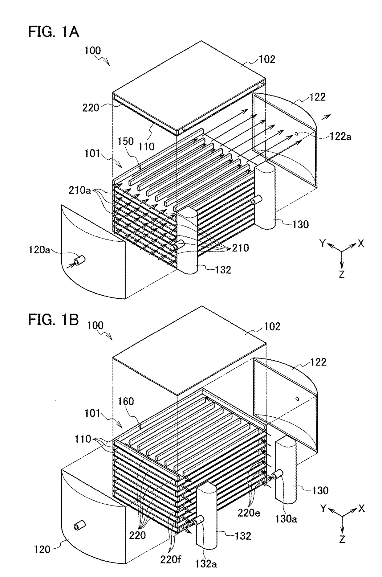
[0023]FIGS. 1A and 1B are exploded perspective views showing a structure of a reactor 100 according to an embodiment of the present disclosure. FIG. 1A is a view illustrating a flow of a reaction fluid, and FIG. 1B is a view illustrating a flow of a heat medium. The reactor 100 is of a heat exchanger-type, and includes a heat exchange body 101, a reaction fluid introduction part 120 and a product drain part 122, and a heat medium introduction part 130 and a heat medium drain part 132. FIG. 1A does not indicate structured catalysts described below for brevity.

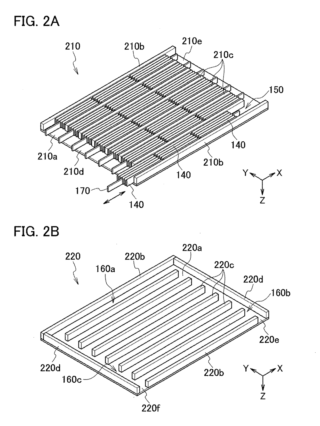
[0024]The heat exchange body 101 has a counter flow-type structure in which a reaction fluid flows in a direction opposite to a flowing direction of a heat medium, and includes a plurality of first heat transfer bodies 210 and second heat transfer bodies 220, and a lid body 102. The heat exchange body 101 is supported by thermal insulating pillars (not shown). The first heat transfer bodies 210, the second heat transfer bodies 2...

second embodiment

[0050]A reactor according to a second embodiment of the present disclosure is described below. While the fundamental structure of the reactor according to the present embodiment is substantially the same as that in the first embodiment, the reactor according to the present embodiment further includes a positioning mechanism for positioning the structured catalysts 140 in the reaction channels 150.

[0051]FIG. 6 is a perspective view partly showing a structure of a positioning mechanism 300 according to the present embodiment. The positioning mechanism 300 includes an engaging part 310a provided at least at one end of an extending part 310b in the extending direction, and a reference member 320 in contact with the engaging part 310a in a state in which a holding member 310 is installed in the reaction channel 150.

[0052]The fundamental structure of the holding member 310 is substantially the same as the holding member 170 in the first embodiment. However, the holding member 310 is chara...


PUM

PropertyMeasurementUnit
shapeaaaaaaaaaa
heataaaaaaaaaa
areaaaaaaaaaaa

Abstract

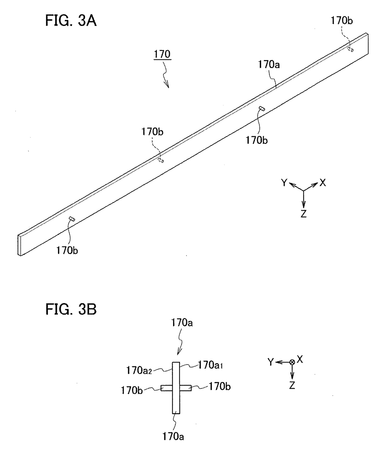
A reactor includes: a heat exchange body including a heat medium channel through which the heat medium flows and a reaction channel through which the reaction fluid flows; at least one structured catalyst supporting a catalyst for promoting the reaction of the reaction fluid and removably installed in the reaction channel; and a holding member including an extending part extending in a direction conforming to an extending direction of the reaction channel and capable of engaging with the at least one structured catalyst, and regulating parts provided in the extending part to regulate a movement of the at least one structured catalyst in the extending direction of the extending part, wherein the holding member is inserted and removed with respect to the reaction channel while holding the structured catalyst.

Description

CROSS REFERENCE TO RELATED APPLICATIONS[0001]This application is a continuation application of International Application No. PCT / JP2017 / 008229, filed on Mar. 2, 2017, which claims priority to Japanese Patent Application No. 2016-041079, filed on Mar. 3, 2016, the entire contents of which are incorporated by reference herein.BACKGROUND1. Technical Field[0002]The present disclosure relates to a heat exchanger-type reactor.2. Description of the Related Art[0003]Heat exchanger-type reactors are known as a chemical reaction apparatus which heats or cools a reaction fluid in a gas or liquid state containing a reaction raw material as a reactant so as to promote a reaction of the reactant. Such a reactor is provided with reaction channels through which a reaction fluid flows and heat medium channels through which a heat medium flows, in which heat exchange between the reaction fluid and the heat medium proceeds during a period from supplying the reaction fluid and the heat medium from the ...

Claims


Application Information

Patent Timeline
Patent Type & Authority Applications(United States)
IPC IPC(8): F28D9/00F28F3/06F28F3/08B01J19/24
CPCF28D9/0075F28F3/06F28F3/08B01J19/248B01J35/02C07B61/00C07C9/02F28F3/025F28F9/02F28F21/083F28F21/087F28D9/0062F28D2021/0022B01J19/249B01J2219/00096B01J2219/2453B01J2219/2458B01J2219/2462B01J2219/2471B01J2219/2479B01J2219/2498B01J35/00B01J35/30
Inventor YOSHINOYA, TAKUYAHONMA, NOBUYUKI
Owner IHI CORP
Learn More