
Edge card adapter

a technology of edge card and adapter, which is applied in the direction of coupling device connection, coupling contact member, multiple conductor connector, etc., can solve the problems of achieve the effect of reducing labor and material cost and high labor and material cos

Active Publication Date: 2018-12-27
BIOSENSE WEBSTER (ISRAEL) LTD
View PDF10 Cites 0 Cited by
  • Summary
  • Abstract
  • Description
  • Claims
  • Application Information

AI Technical Summary

Benefits of technology

The invention provides an adapter that simplifies the assembly of catheter handles, reduces labor and material costs, and allows the use of inexpensive PCBs. The adapter can accommodate a flexible PCB and a rigid PCB, providing flexibility and durability in catheter handle design.

Problems solved by technology

Application of the existing methods to a catheter handle design incurs a high labor and material cost, as the use of relatively expensive flex-rigid PCB is required to meet spatial constraints in a catheter handle.

Method used


Image

  • Edge card adapter
  • Edge card adapter
  • Edge card adapter

Examples


Embodiment Construction

[0028]In the following description, numerous specific details are set forth in order to provide a thorough understanding of the various principles of the present invention. It will be apparent to one skilled in the art, however, that not all these details are necessarily needed for practicing the present invention.

[0029]Documents incorporated by reference herein are to be considered an integral part of the application except that, to the extent that any terms are defined in these incorporated documents in a manner that conflicts with definitions made explicitly or implicitly in the present specification, only the definitions in the present specification should be considered.

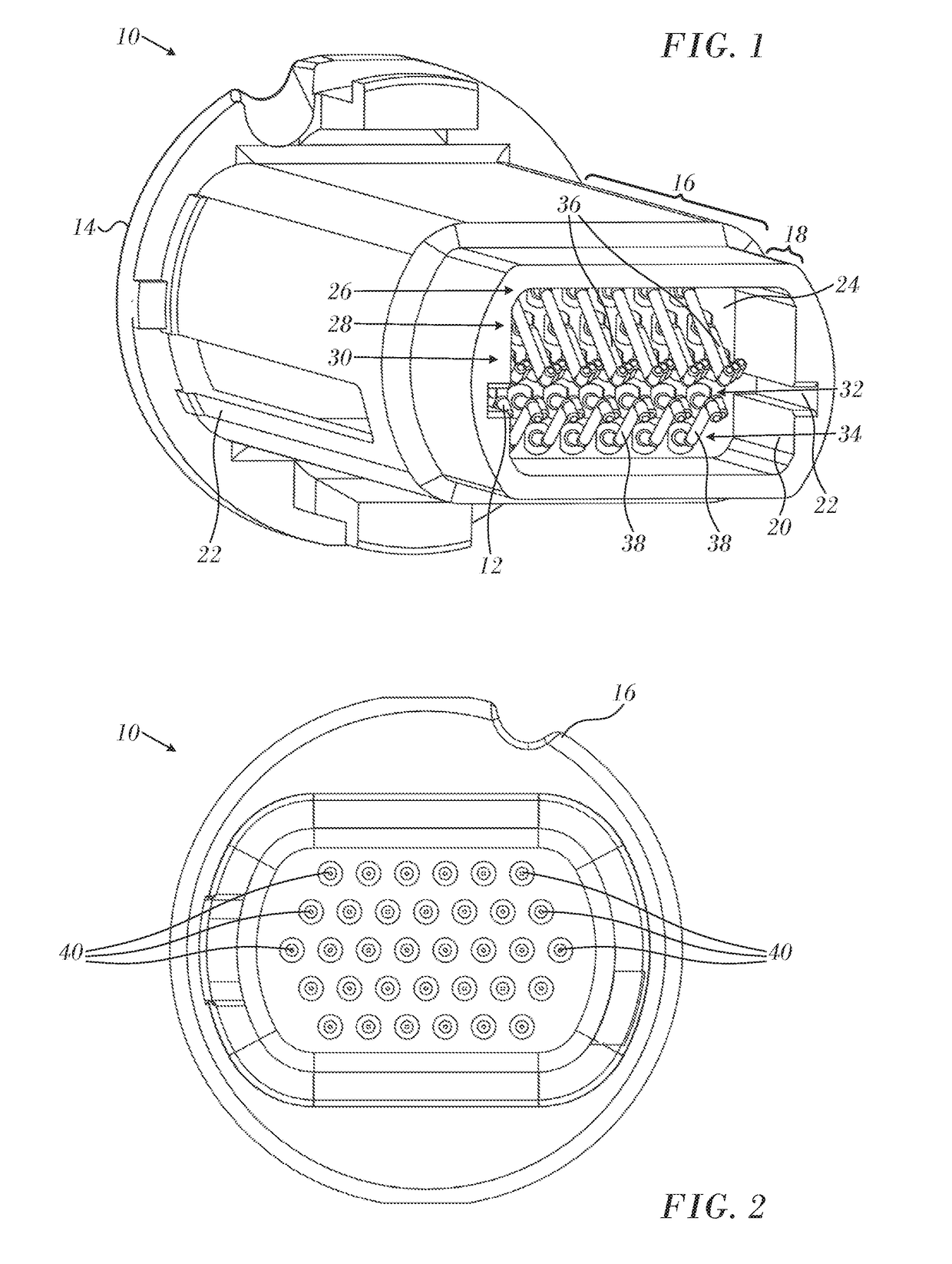
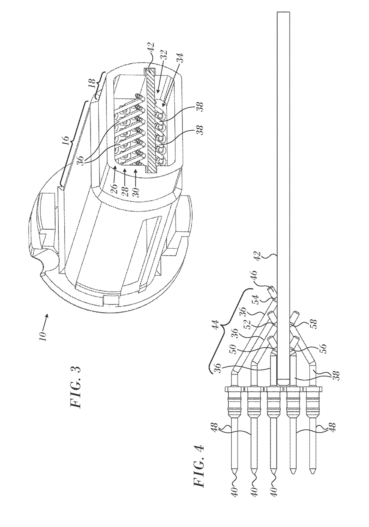
[0030]Turning now to the drawings, reference is initially made to FIG. 1, which is an oblique sectional card-side (frontal) elevation through an edge card adapter 10 in accordance with an embodiment of the invention. Edge card adapter 10 has a housing 12, a rear flange 14, which is adapted for connection to a cab...


PUM


Abstract

An edge card connector assembly has a harness-side portion connectable to a cable and a card-side portion adapted to receive a planar structure edgewise therein in a plane of entry. The edge card connector has a plurality of resilient electrical contacting members extending through the wall and is adapted for electrical connection with the cable in the harness-side portion and with the planar structure in the card-side portion. Upper and lower contacting members are disposed above and below the plane, respectively, such that the received planar structure impinges on the contacting members to urge the upper and lower contacting members away from the plane, and the upper and lower contacting members exert opposing holding pressure on the upper and lower surfaces of the planar structure at respective contact points.

Description

COPYRIGHT NOTICE[0001]A portion of the disclosure of this patent document contains material that is subject to copyright protection. The copyright owner has no objection to the facsimile reproduction by anyone of the patent document or the patent disclosure, as it appears in the Patent and Trademark Office patent file or records, but otherwise reserves all copyright rights whatsoever.BACKGROUND OF THE INVENTION1. Field of the Invention[0002]This invention relates to electrical coupling devices. More particularly, this invention relates to an electrical coupling device for coupling with the edge of planar structures such as rigid printed circuit boards.2. Description of the Related Art[0003]The meanings of certain acronyms and abbreviations used herein are given in Table 1.TABLE 1Acronyms and AbbreviationsPCBPrinted Circuit BoardHSSDCHigh Speed Serial Data Connector[0004]Connecting to circuitry formed on a printed circuit board (PCB) typically requires soldering wires and connectors ...

Claims


Application Information

Patent Timeline
Patent Type & Authority Applications(United States)
IPC IPC(8): H01R13/24H01R11/03H01R12/70H01R24/28H01R24/20H01R13/516H01R12/72H01R43/20
CPCH01R13/2457H01R11/03H01R13/2492H01R12/7029H01R43/205H01R24/20H01R13/516H01R12/72H01R24/28H01R13/24H01R13/46H01R13/665H01R12/721H01R12/714H01R12/75H01R2201/12
Inventor BEN SHOSHAN, SHARONA
Owner BIOSENSE WEBSTER (ISRAEL) LTD
Learn More