An elbow assembly of a patient interface, an Anti-asphyxia valve for an elbow assembly and a connector

a patient interface and elbow assembly technology, applied in the field of elbow assembly of a patient interface, can solve the problems of bias-flow venting system becoming a source of discernable noise, the aa valve in such elbow assembly does not open or close fully or reliably, and the user's nose being elevated, etc., to achieve the effect of reducing noise, improving cleaning ease, and improving the compactness of the respiratory mask

Pending Publication Date: 2019-01-03
FISHER & PAYKEL HEALTHCARE LTD
View PDF6 Cites 37 Cited by
  • Summary
  • Abstract
  • Description
  • Claims
  • Application Information

AI Technical Summary

Benefits of technology

[0006]A large variety of respiratory masks have been devised. Many of these masks are configured to provide sealed communication with a user's airway, by sealing around parts of the user's nose and / or mouth. These masks are commonly used to provide therapies, such as, but not limited to, non-invasive ventilation (NIV) and constant positive airway pressure (CPAP). CPAP therapy is commonly used to treat obstructive sleep apnea (OSA) and involves providing a constant supply of pressurized air to a user's airway. This splints the airway open, thus minimizing airway collapse and reducing apneas. As part of this therapy, a bias-flow venting system is used to flush exhaled carbon dioxide (CO2) from within the mask, which reduces or eliminates the likelihood of rebreathing.
[0078]In some embodiments, a transitional wall is defined between the at least one linear bead portion and the remainder of the valve flap, the transitional wall extending from a margin of the linear bead portion to the body of the flap, the transitional wall being configured to provide structural stiffness to the flap.

Problems solved by technology

In order to sufficiently reduce leakage, the headgear typically is tightened, which results in an elevated pressure being exerted on a bridge of a user's nose.
It can be a problem that AA valves in such elbow assemblies do not open or close fully or reliably.
Bias-flow venting systems can become a source of discernable noise.
Drafts can be annoying to both the user and / or their bed partner and may result in reduced compliance with the therapy.
Bias-flow venting systems can also be difficult to clean, which may result in contamination or reduced compliance with the therapy.
Such bias-flow venting systems can also add bulk to the respiratory mask, further reducing the user's comfort while wearing the respiratory mask and, thus, the user's likelihood of complying.
Other common problems experienced in relation to current headgear include the headgear being too heavy, bulky and hot, which can be uncomfortable for the user.
Headgear made from traditional materials can be slow to dry after being washed.
This can impact patients because often the headgear will not dry within a day and patients will be forced to either not wear their mask or wear it with wet headgear.
This inconvenience associated with cleaning of the headgear can lead to some patients choosing not to wash the headgear at all, which can become unhygienic.

Method used


Image

  • An elbow assembly of a patient interface, an Anti-asphyxia valve for an elbow assembly and a connector
  • An elbow assembly of a patient interface, an Anti-asphyxia valve for an elbow assembly and a connector
  • An elbow assembly of a patient interface, an Anti-asphyxia valve for an elbow assembly and a connector

Examples


embodiment 19

[0506]k) Support block 954 thickness to hinge 960 thickness: may be between 5:1 and 30:1, more preferably 10:1 to 25:1, more preferably 15:1 to 25:1, and in one preferred 1.

embodiment 3

[0507]1) Valve flap 952 thickness in the region of upper planar surface 972 between the bead to hinge 960 thickness: may be between 1:1 and 10:1, more preferably 1:1 to 8:1, more preferably 2:1 to 5:1, and in one preferred 1.

[0508]m) Valve flap 952 thickness in the region of upper planar surface 972 between the bead to the thickness of the bead region 964a above recess 965: may be between 1:1 and 10:1, more preferably 1:1 to 8:1, more preferably 2:1 to 5:1, and in one preferred embodiment 2.5:1.

[0509]n) Valve flap 952 thickness in the region of upper planar surface 972 between the bead to thickness of the inclined wall 964b: may be between 1:1 and 10:1, more preferably 1:1 to 5:1, more preferably 1:1 to 2:1, and in one preferred embodiment 1.4:1.

[0510]o) Valve flap 952 thickness in the region of upper planar surface 972 between the bead to thickness of the bead region 964a above recess 965: may be between 1:1 and 10:1, more preferably 1:1 to 5:1, more preferably 2:1 to 3:1, and in o...

embodiment 13

[0513]r) Width of bead region 964a to thickness of the bead region 964a above recess 965: may be between 1:1 and 30:1, more preferably 1:1 to 20:1, more preferably 1:1 to 15:1, and in one preferred 1.

Annular Bias-Flow Venting

[0514]For a more detailed understanding of the disclosure, reference is first made to FIG. 32, which shows a breathing circuit according to at least one embodiment, which includes a respiratory mask.

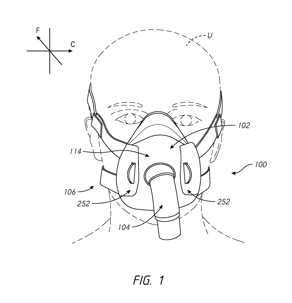
[0515]FIG. 32 is a schematic diagram of a positive pressure respiratory therapy system in the form of a continuous positive airway pressure (CPAP) system 1010 for providing a heated and humidified air stream to a user U through an interface 1110 worn by the user, and which is connected to CPAP system 1010 by a conduit or tube 1012. A humidification chamber 1014 has a heat conductive base in contact with a heater plate 1016 of a humidifier 1017 to humidify the air stream. The conduit 1012 is connected to an outlet 1013 of the humidification chamber 1014 to convey humi...


PUM


Abstract

An interface for positive pressure therapy includes a mask assembly, a headgear assembly and a connection port assembly. The mask assembly comprises a seal member that has an upper portion movably connected to an integrated lower portion, wherein the upper portion rolls during hinging movement of the upper portion relative to the lower portion. The headgear assembly allows connection to the mask assembly in a direction substantially normal to a direction of strap tension. The connection port assembly includes a swivel elbow with a valve member that controls flow through a port that opens toward the user. The valve member is provided with a tapered bead that helps prevent the valve member from sticking in a given position. Also, a connector for connecting a respiratory tube to an elbow connector.

Description

REFERENCED DISCLOSURES[0001]The present disclosure references various features of U.S. Patent Application No. 62 / 199,513, filed 31 Jul. 2015, U.S. Patent Application No. 62 / 199,547, filed 31 Jul. 2015, U.S. Patent Application No. 62 / 209,822, filed 25 Aug. 2015, U.S. Patent Application No. 62 / 232,293, filed 24 Sep. 2015, U.S. Patent Application No. 62 / 305,284, filed Mar. 8, 2016, U.S. Patent Application No. 62 / 358,790, filed Jul. 6, 2016, and U.S. Patent Application No. 62 / 360,052, filed Jul. 8, 2016. The entire disclosures of those applications are hereby made part of this specification as if set forth fully herein and incorporated by reference for all purposes, for all that they contain.FIELD OF THE DISCLOSURE[0002]The present invention generally relates to patient interfaces for respiratory therapy. The present invention generally relates to an elbow assembly of a patient interface such as a face mask that covers at least one of a nose and a mouth of a user to supply respiratory g...

Claims


Application Information

Patent Timeline
Patent Type & Authority Applications(United States)
IPC IPC(8): A61M16/08A61M16/06A61M16/20A61M16/00
CPCA61M16/0825A61M16/0633A61M16/208A61M16/0069A61M2205/42A61M16/0683A61M2207/00A61M2209/06A61M16/0605
Inventor ROSE, HAMISH JOSHUAPEDERSEN, MATTHEW JAMESPRENTICE, CRAIG ROBERTSPEAR, TONY WILLIAMWALLS, BRUCE MICHAELWILLFROTH, DANAMITTERMEIER, SIMONBORNHOLDT, MELISSA CATHERINEOLSEN, GREGORY JAMES
Owner FISHER & PAYKEL HEALTHCARE LTD
Why Eureka
Try Eureka