Water cooled engine

a water-cooled engine and engine technology, applied in the direction of engine cooling apparatus, liquid cooling, cylinders, etc., can solve the problems of increasing the the temperature of the exhaust gas may rise, etc., and achieves the effects of low thermal strain of the cylinder head, high cooling performance, and reduced thermal strain

Active Publication Date: 2019-01-03
KUBOTA LTD
View PDF17 Cites 2 Cited by
  • Summary
  • Abstract
  • Description
  • Claims
  • Application Information

AI Technical Summary

Benefits of technology

[0003]An object of the present invention is to provide a water cooled engine including a cylinder head with minimized thermal strain.
[0008]According to the present invention, thermal strain of the cylinder head is minimized.
[0009]According to the present invention, high cooling performance is achieved at the first exhaust entrance port wall.
[0010]According to the present invention, high cooling performance is achieved at the first exhaust entrance port wall and the second exhaust entrance port wall.

Problems solved by technology

When output is increased with a conventional water cooled engine, the temperature of the exhaust gas may rise and cooling may become insufficient at the exhaust side, inviting an increase in thermal strain of the cylinder head.

Method used


Image

  • Water cooled engine
  • Water cooled engine
  • Water cooled engine

Examples


Embodiment Construction

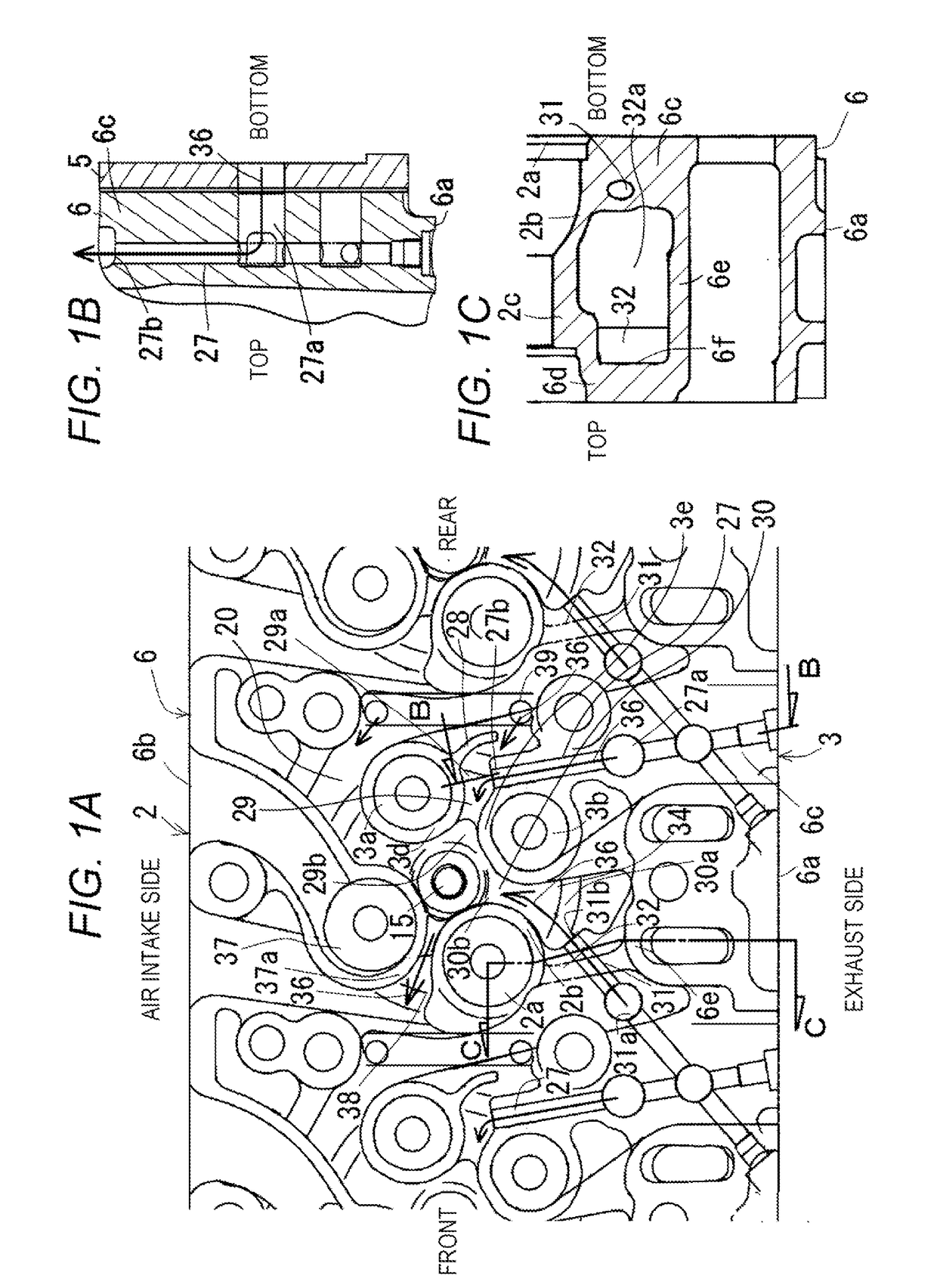
[0020]FIGS. 1A to 1C are illustrations describing a water cooled engine according to an embodiment of the present invention. In the present embodiment, a description will be given of a water-cooled common-rail inline four-cylinder diesel engine.

[0021]The overview of the engine is as follows.

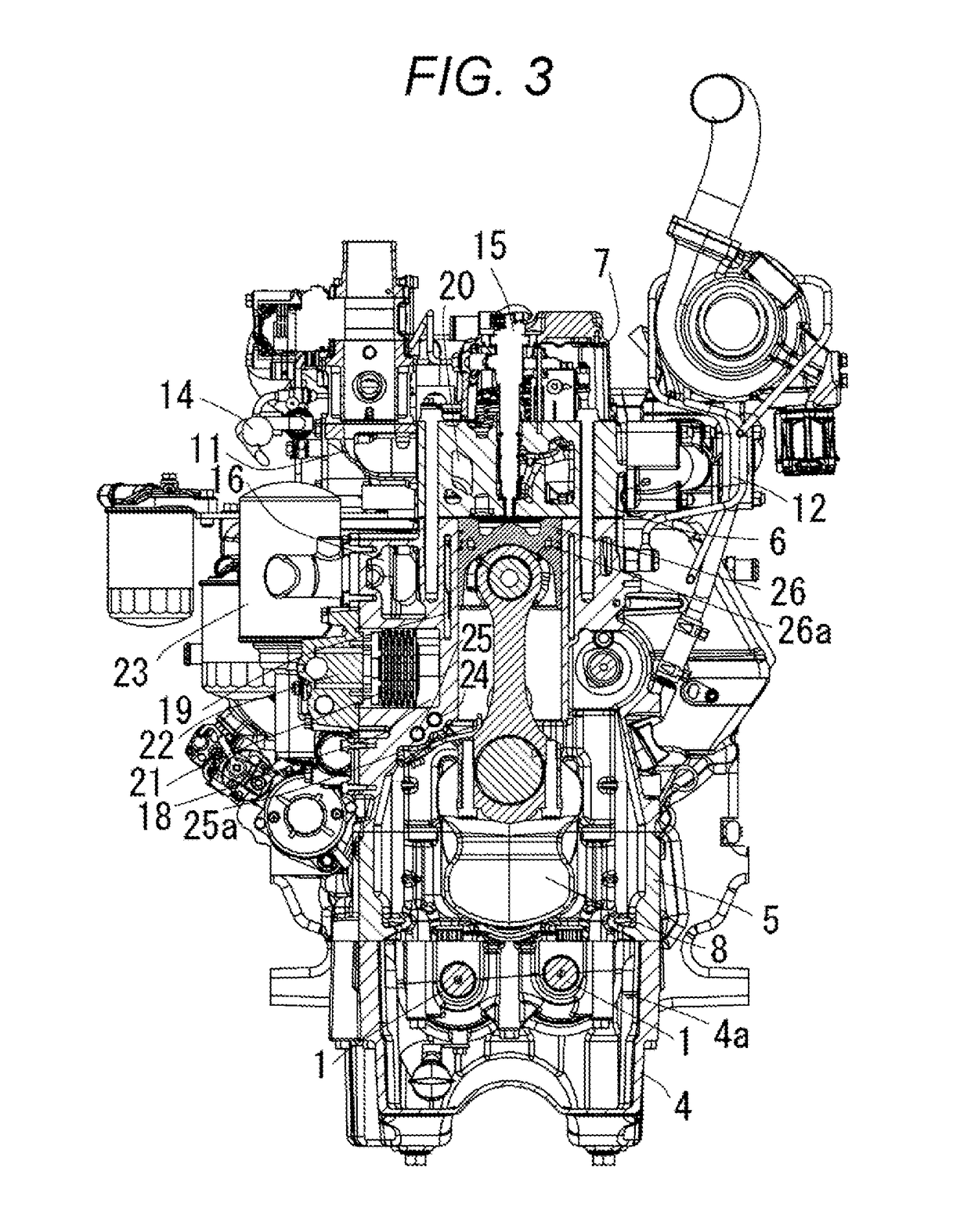
[0022]As shown in FIG. 3, the engine includes: a cylinder block (5); a cylinder head (6) mounted on an upper part of the cylinder block (5); a cylinder head cover (7) mounted on an upper part of the cylinder head (6); an oil pan (4) mounted on a lower part of the cylinder block (5); a belt transmission mechanism (9) disposed at a front part of the cylinder block (5) as shown in FIG. 4 where an extending direction of the crankshaft (8) is a front-rear direction; a flywheel housing (10) disposed at a rear part of the cylinder block (5); an intake manifold (11) provided on laterally one side of the cylinder head (6) as shown in FIG. 3 where a width direction of the engine being perpendicular to the ...


PUM


Abstract

A water cooled engine is provided, including a cylinder head with minimized thermal strain. A head water jacket includes an inter-exhaust-port-wall water channel between a first exhaust entrance port wall and a second exhaust entrance port wall. The cylinder head includes a cooling water injection passage provided at a bottom wall thereof. The cooling water injection passage is positioned on the exhaust end side, and includes a passage entrance provided on the exhaust end side, and a passage exit directed toward the inter-exhaust-port-wall water channel. An exhaust port wall includes a heat dissipation fin extending from a first exhaust entrance port wall toward an exhaust end. The space between the heat dissipation fin and a second exhaust entrance port wall forms a water channel entrance of the inter-exhaust-port-wall water channel.

Description

BACKGROUND OF THE INVENTION(1) Field of the Invention[0001]The present invention relates to a water cooled engine.(2) Description of Related Art[0002]When output is increased with a conventional water cooled engine, the temperature of the exhaust gas may rise and cooling may become insufficient at the exhaust side, inviting an increase in thermal strain of the cylinder head.SUMMARY OF THE INVENTION[0003]An object of the present invention is to provide a water cooled engine including a cylinder head with minimized thermal strain.[0004]The major configuration of the present invention are as follows.[0005]A cylinder head includes a cooling water injection passage provided at a bottom wall of the cylinder head, the cooling water injection passage being positioned (biased) on an exhaust end side, and including a passage entrance provided on the exhaust end side and a passage exit directed toward an inter-exhaust-port-wall water channel.[0006]An exhaust port wall includes a heat dissipati...

Claims


Application Information

Patent Timeline
Patent Type & Authority Applications(United States)
IPC IPC(8): F02F1/40F02F1/42
CPCF02F1/40F02F1/4214F02F1/4285F01P3/02F01P2003/024F01P3/14F01P3/16F02F1/242F02F1/38
Inventor SUGIMOTO, SATOSHIKOMEMUSHI, YUSUKEWADA, NAOKI
Owner KUBOTA LTD
Why Eureka
Try Eureka