Optical breadboard table and method

a technology of optical breadboards and breadboards, applied in the direction of optical apparatus testing, instruments, machine supports, etc., can solve the problems of compromising the precision of component placement and spatial distance on the outer surface of the component affixed to the outer surface, and the core structure is often ineffective in minimizing and absorbing the effects and vibration transfer,

Inactive Publication Date: 2020-03-26
FISHER JAMES
View PDF0 Cites 0 Cited by
  • Summary
  • Abstract
  • Description
  • Claims
  • Application Information

AI Technical Summary

Benefits of technology

[0016]From another perspective, the present invention provides an optical breadboard table comprising: a core defining a core upper surface; a fastening layer defining a fastening layer upper surface and a fastening layer bottom surface and a plurality of spaced apart threaded fastening apertures, each defining a threaded diameter, the threaded fastening apertures being arranged in a pre-determined pattern, the fastening layer bottom surface being joined to the core upper surface; a top skin defining a top skin upper surface and a top skin bottom surface and a plurality of spaced apart clearance apertures, each defining a clearance diameter greater than the threaded diameters, the clearance apertures being arranged in the pre-determined pattern and in registry with the threaded fastening apertures, the top skin bottom surface being joined to the fastening layer upper surface, whereby optical apparatus may be positioned upon the top skin upper surface and secured thereon by a plurality of threaded fasteners passing through selected ones of the clearance apertures and threadably engaging underlying ones of the plurality of threaded fastening apertures such that attachment stress upon the top skin is minimized.

Problems solved by technology

These demands, in turn, expose problems in many typical optical table designs.
For example, the core structures are often ineffective in minimizing and absorbing the effects and transfer of vibrations.
Other problems arise due to liquid contamination of the core materials in the event the top surface is exposed to liquid which runs downwardly through the threaded apertures of the top skin into the core.
A significant problem arises due to temperature effects as the ambient temperature surrounding the optical breadboard, table or similar structure produces thermal strain (expansion or contraction) of the table material which, in turn, alters and compromises the precision of component placement and spatial distance on those components affixed to the outer surface.

Method used


Image

  • Optical breadboard table and method
  • Optical breadboard table and method
  • Optical breadboard table and method

Examples


Embodiment Construction

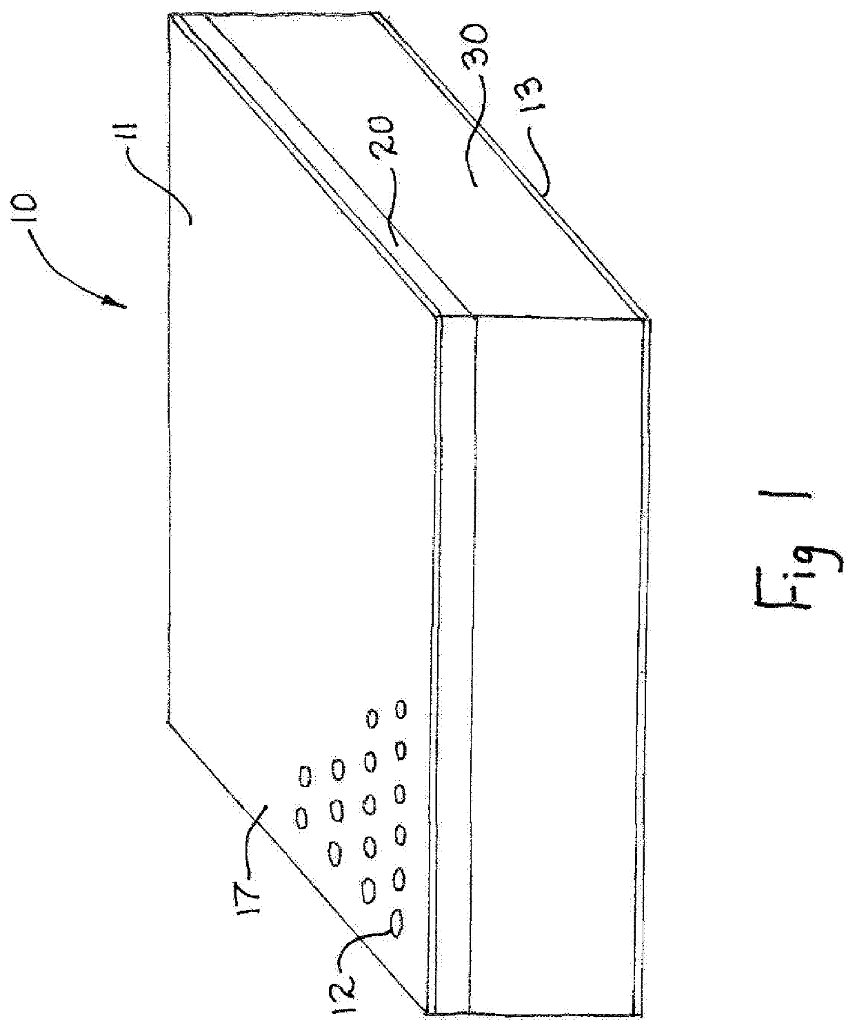
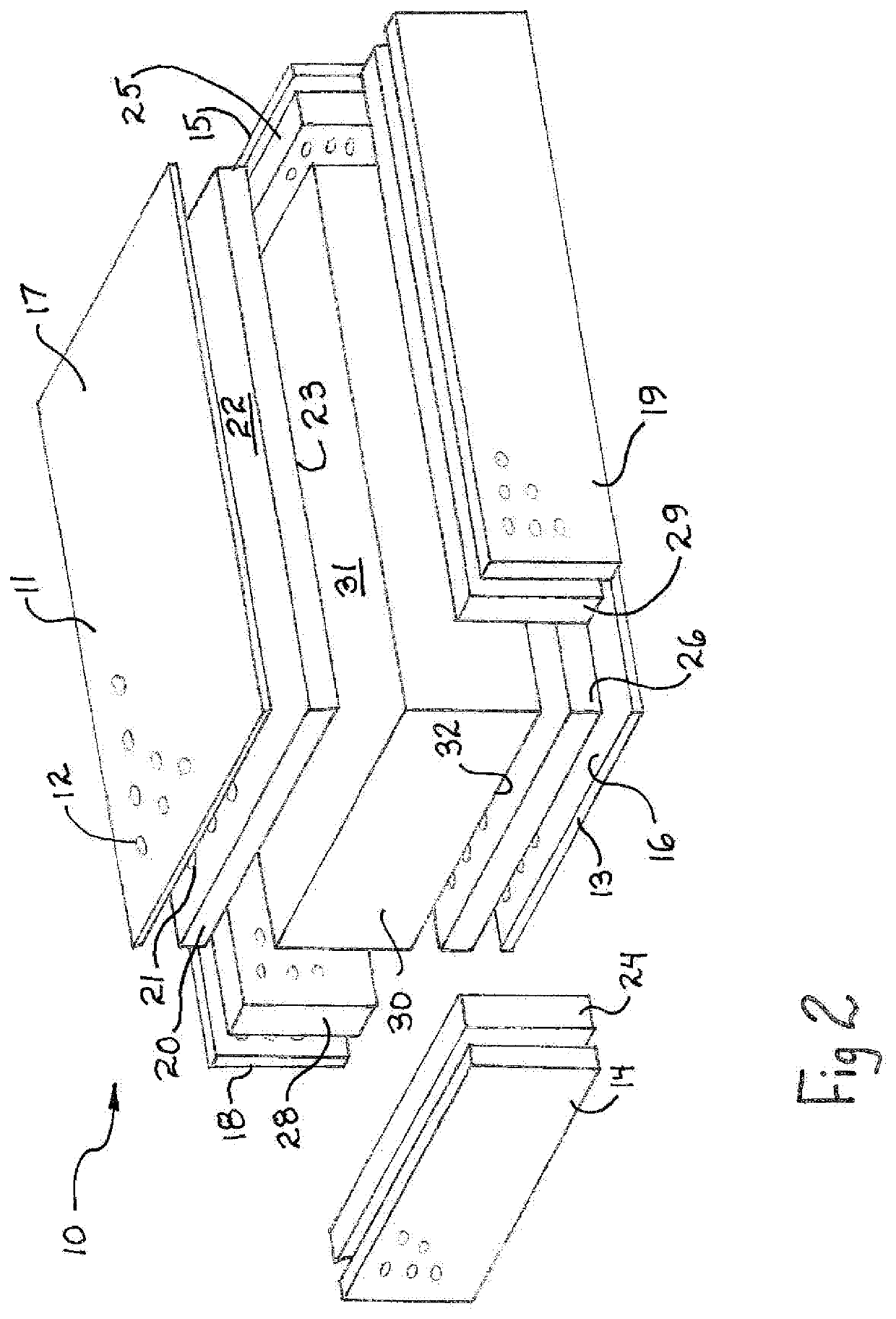
[0029]By way of overview, the present invention provides an improved optical breadboard table and method in which a table top having a top skin defining a plurality of clearance apertures, a core and a bottom skin is improved by adding a fastening layer interposed between the top skin and the upper surface of the core. The fastening layer defines a plurality of threaded apertures in alignment and registration with the plurality of clearance apertures formed in the top skin. The threaded apertures are each sized to facilitate the insertion of threaded fasteners through the clearance apertures of the top skin to threadably engage the threaded apertures of the fastening layer. In this manner, the thickness of the top skin may be substantially reduced, or comprised of composite material, because the need for forming threads within the top skin apertures is avoided. The top skin, fastening layer, core and bottom skin are joined by conventional attachment such as adhesive attachment, weld...


PUM


Abstract

A composite structure includes a top skin defining a plurality of clearance apertures, a core and a bottom skin together with a fastening layer interposed between the top skin and the upper surface of the core. The fastening layer defines a plurality of threaded apertures in alignment and registration with the plurality of clearance apertures formed in the top skin. The threaded apertures each define a threaded aperture size which facilitates threaded fasteners being passed through the clearance apertures of the top skin to threadably engage the threaded apertures of the fastening layer. The top skin, fastening layer, core and bottom skin are joined by conventional attachment such as adhesive attachment, welding or the like.

Description

CROSS-REFERENCE TO RELATED APPLICATION[0001]This application claims the benefit of and priority under 35 U.S.C. 119(e) of U.S. Provisional Patent Application No. 62 / 680,141 entitled OPTICAL BREADBOARD TABLE AND METHOD, filed Jun. 4, 2018 in the name of James Fisher, the disclosure of which is incorporated herein by reference.FIELD OF THE INVENTION[0002]This invention relates generally to optical breadboards, optical tables and similar structures and particularly to apparatus and methods utilized therein for facilitating the use of threaded fasteners to removably secure a plurality of optical and mechanical components to the table for purposes of study, experiment and production.BACKGROUND OF THE INVENTION[0003]Optical breadboards, tables and similar structures of the type toward which the present invention is directed are prevalent within the fields of optical sciences, studies and experimentation. Other fields of scientific endeavor also frequently find use for optical breadboard, ...

Claims


Application Information

Patent Timeline
Patent Type & Authority Applications(United States)
IPC IPC(8): G02B7/00F16M11/04G01M11/04
CPCF16M11/04G01M11/04G02B7/008
Inventor FISHER, JAMES
Owner FISHER JAMES
Why Eureka
Try Eureka