Braid construction to match coefficients of thermal expansion for composite transmission housings

Inactive Publication Date: 2006-07-06
SIKORSKY AIRCRAFT
View PDF5 Cites 0 Cited by
  • Summary
  • Abstract
  • Description
  • Claims
  • Application Information

AI Technical Summary

Benefits of technology

[0009] In one composite transmission component example, the composite transmission component is positioned radially inward from the metal transmission component. The first CTE is tailored to be generally equal to the CTE of the second composite component in an axial direction and the second CTE is tailored to be slightly greater than or equal to the CTE of the metal transmission component in a hoop direction to minimize thermal strain between all the components and to maintain a tight fit between the composite transmission component and the metal transmission component.
[0010] In another composite transmission component example, the composite transmission component is positioned radially outward from the metal transmission component. The first CTE is tailored to be generally equal to the CTE of the second composite component in an axial direction and the second CTE is tailored to be slightly greater than or equal to the CTE of the metal transmission component in a hoop direction to minimize thermal strain between all the components and to maintain a tight fit between the composite transmission component and the metal transmission component.

Problems solved by technology

The use of composite components and metallic components in intimate contact with each other may present problems over the operating temperature range of the power transmission.
When the composite component and metal component are bonded together or otherwise meet at a composite-metal interface, the difference in CTE may cause thermal strain between the composite component and the metal component, which in turn may lead to a failure at the composite-metal interface.
Common interface failures include physical separation between the composite component and metal component, aggravated fatigue and creep, formation of leak paths, and loosening of press fits, all of which may affect the proper functioning of the power transmission.
The problem is further compounded with an additional composite-composite interface when another composite component with yet another CTE is located next to the first composite component.
These conventional composites typically include stacking positive and negative CTE composite layers, using specialized and expensive fibers, or orienting the reinforcing fibers to tailor the CTE in a single direction.
Although these conventional composites may alleviate thermal strain problems for composite-metal interfaces, a conventional composite may actually aggravate thermal strain problems in a power transmission application where the composite component also interfaces with another different type of composite component by increasing the difference between the CTE's of the two composite components.

Method used


Image

  • Braid construction to match coefficients of thermal expansion for composite transmission housings
  • Braid construction to match coefficients of thermal expansion for composite transmission housings
  • Braid construction to match coefficients of thermal expansion for composite transmission housings

Examples


Embodiment Construction

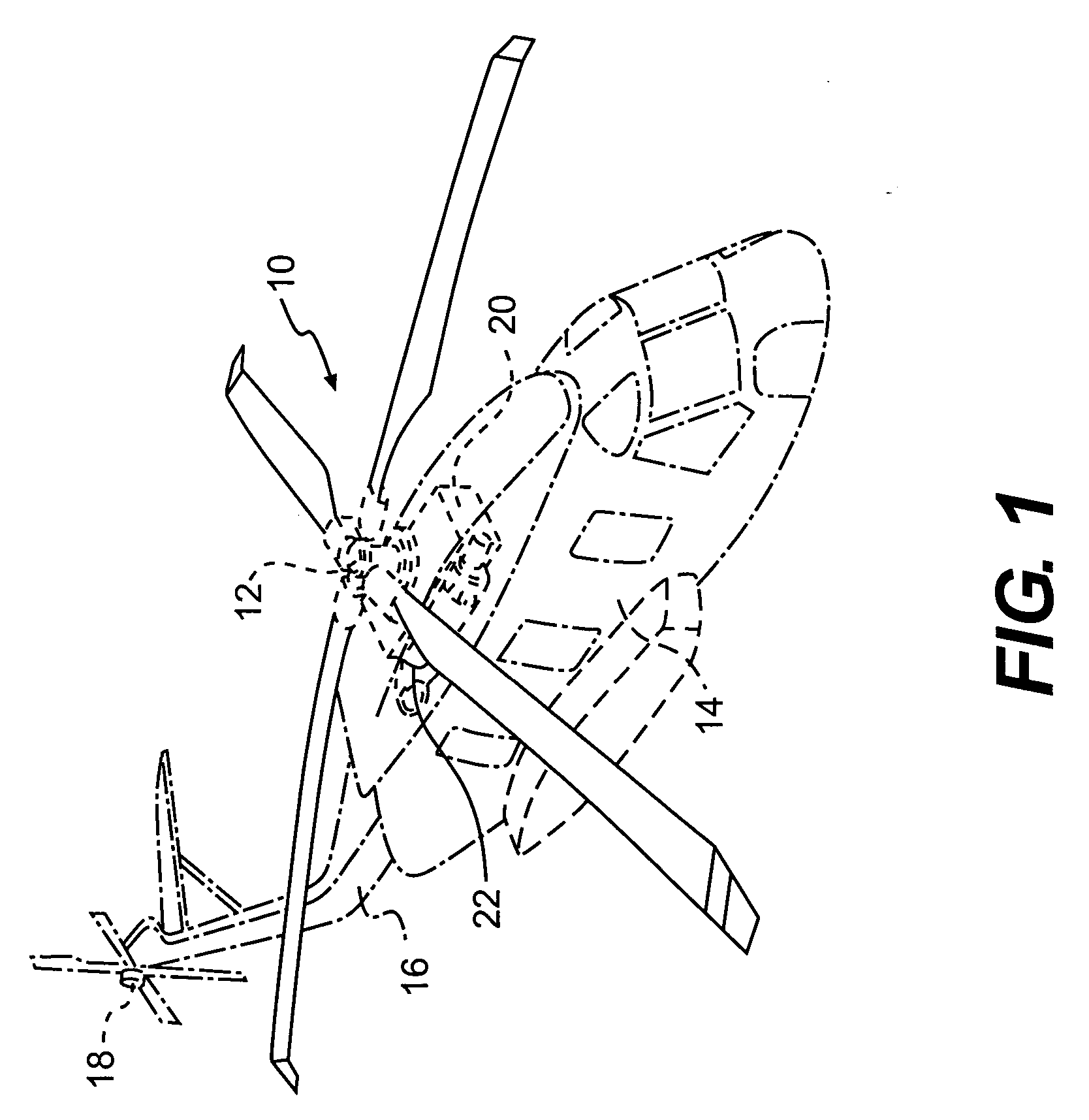
[0017]FIG. 1 schematically illustrates a rotary-wing aircraft 10 having a main rotor assembly 12. The aircraft 10 includes an airframe 14 having an extending tail 16 which mounts an anti-torque rotor 18. The main rotor assembly 12 is driven through a transmission (illustrated schematically at 20) by one or more engines 22. Although a particular helicopter configuration is illustrated in the disclosed embodiment, other machines such as turbo-props, tilt-rotor and tilt-wing aircraft will also benefit from the present invention.

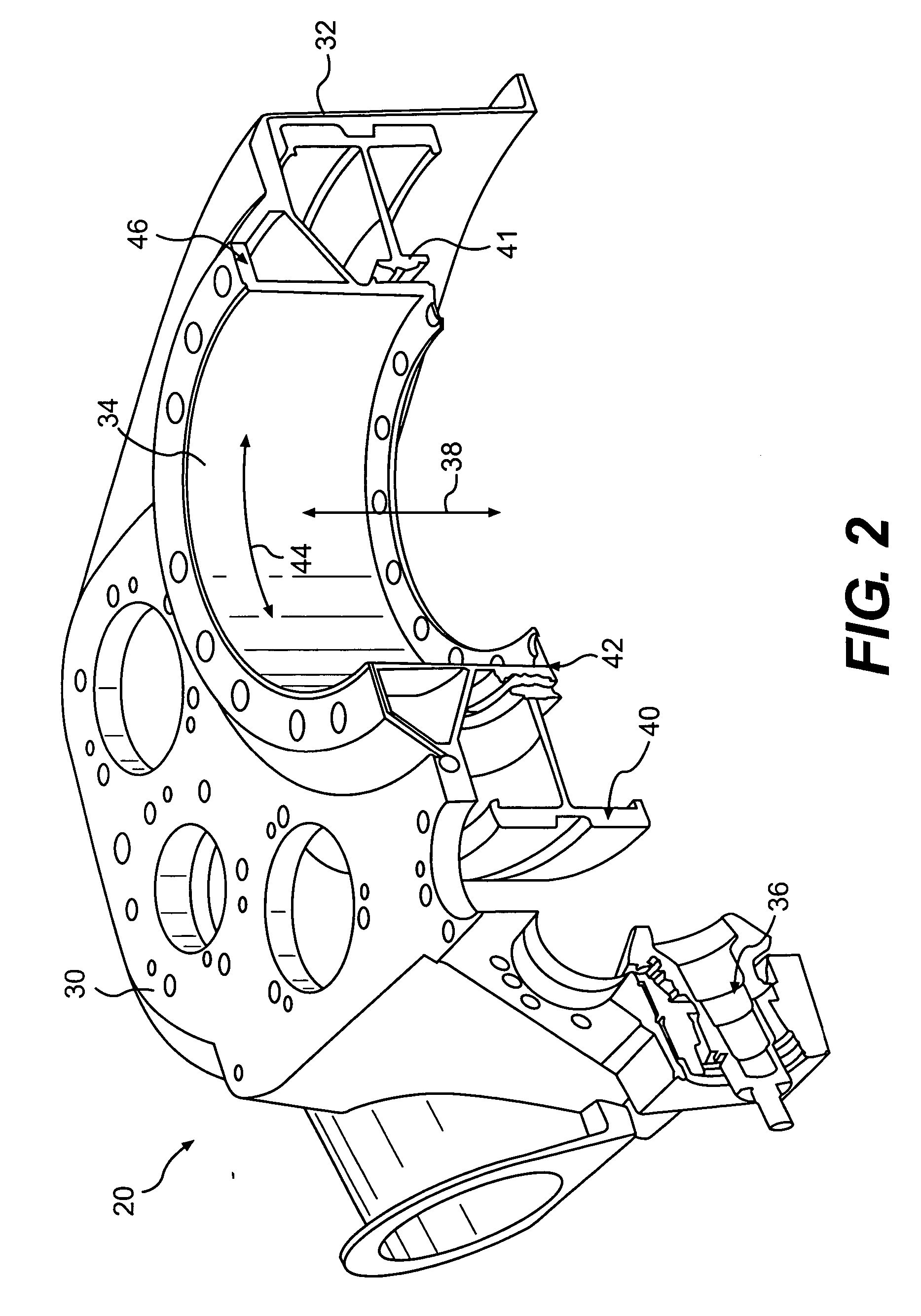
[0018] Referring to FIG. 2, the transmission 20 includes a transmission housing 30. The transmission housing 30 includes a composite outer structure 32 which is preferably fabricated from a graphite fiber reinforced composite. The composite outer structure 32 structurally supports an adjacent first composite support 34 and tail rotor take off drive 36.

[0019] The first composite support 34 is annular in shape and defines an axis 38. A bull gear 40 with a steel ...


PUM

PropertyMeasurementUnit
Angleaaaaaaaaaa
Angleaaaaaaaaaa
Angleaaaaaaaaaa

Abstract

A transmission assembly includes a composite transmission component with a tailored coefficient of thermal expansion (CTE). The composite transmission component is fabricated from graphite axial fibers and S-glass bias fibers that are oriented at a bias angle to the graphite axial fibers. The composite transmission component is located adjacent to a second composite transmission component and a metal transmission component. A first CTE of the composite transmission component is tailored to a CTE of the second composite component. A second CTE of the composite transmission component is tailored to a metal CTE of the metal transmission component. The first and second CTE are tailored by utilizing graphite axial fibers and S-glass bias fibers, or two other different types of fibers, and by controlling the bias angle. The tailored first and second CTE minimize thermal strain and maintain a tight fit between the components.

Description

BACKGROUND OF THE INVENTION [0001] This invention relates to transmission housings and, more particularly, to a composite transmission housing component with a tailored coefficient of thermal expansion (CTE). [0002] Conventional power transmissions and transmission components may potentially use light-weight composite materials to reduce the weight of the power transmission, however, some components such as gears, bearing liners, and bearing races are still made from metal materials. [0003] The use of composite components and metallic components in intimate contact with each other may present problems over the operating temperature range of the power transmission. Typically, the composite component has a different CTE than the metal component. The difference in CTE causes the composite component to expand and contract over a temperature range differently than the metal component expands and contracts. When the composite component and metal component are bonded together or otherwise ...

Claims


Application Information

Patent Timeline
IPC IPC(8): D03D15/04D03D15/00D03D15/567
CPCD04C1/06D10B2505/02F16H57/032Y10T442/326Y10T442/3228Y10T442/3195Y10T442/3236Y10T442/3252Y10T442/3179Y10T442/322
Inventor DAVIS, GEOFFREY CLIVE ROBERTGARHART, JONATHAN KENT
Owner SIKORSKY AIRCRAFT
Why Eureka
Try Eureka