A thermal storage system and temperature controlled container comprising the same

a technology of thermal storage and temperature control, which is applied in the direction of lighting and heating apparatus, heating types, domestic cooling apparatus, etc., can solve the problems of large heat absorption, unsuitable for thermal energy storage applications at other temperature levels, etc., and achieves efficient circulation, fast charging or discharging, and reduce the overall size of the thermal storage unit

Inactive Publication Date: 2019-01-03
UNIV GENT +1
View PDF0 Cites 14 Cited by
  • Summary
  • Abstract
  • Description
  • Claims
  • Application Information

AI Technical Summary

Benefits of technology

[0012]It has been found that by providing the at least one FT unit with a heat transfer fluid, which is maintained in the passageway of the at least one FT unit upon disconnection of the heat transfer fluid system, a larger thermal energy density is obtained compared to the systems of the prior art. The thermal energy density is the amount of thermal energy stored in the thermal storage system per unit of volume of the thermal storage system. In the case where the heat transfer fluid is a multi phase fluid of which at least one substance changes phase during heat transfer the thermal energy density may be significantly higher due to the latent contribution during phase change of the heat transfer fluid, which is not available when using a single phase heat transfer fluid which only has a sensible heat contribution. Moreover, the heat transfer coefficient of a multi phase fluid of which at least one substance changes phase during heat transfer may also be significantly higher than the heat transfer coefficient of a single phase fluid. This may significantly increase the faster transfer of thermal energy between the first FT and HS unit, even when for example the heat transfer fluid is not maintained in the passageway of the at least one FT unit upon disconnection of the heat transfer fluid system.
[0023]According to embodiments of the present invention, the heat conducting elements are in the form of a porous structure having a predetermined porosity. The volumetric porosity of this porous structure may be between 75% and 98%, preferably between 88% and 95% with respect to the volume of the porous structure. It has been found that by providing a highly porous structure the volume taken by this structure otherwise lost to add PCM is limited. For example, the porous structure is made of metal foam. Structures like metal foam allow thermal energy to be distributed more efficiently throughout the first PCM material making it possible to use the volume of the PCM material more efficiently and thus make it possible to more efficiently use the HS unit by making more use of the possibility of more efficiently transporting the thermal energy inside the first PCM material and not only of the contact surface of the HS unit. The metal foam has a surface-to-volume ratio (SVR) ranging from 300 m2 / m3 to 1500 m2 / m3 measured using a micro computed tomography scanning technique. The metal foam has an average cell diameter of 10 mm or smaller measured using a micro computed tomography scanning technique.

Problems solved by technology

Conversely, when such material melts, it absorbs a large amount of heat for instance from the environment.
), which makes it unsuitable for thermal energy storage applications at other temperature levels.

Method used


Image

  • A thermal storage system and temperature controlled container comprising the same
  • A thermal storage system and temperature controlled container comprising the same
  • A thermal storage system and temperature controlled container comprising the same

Examples


Embodiment Construction

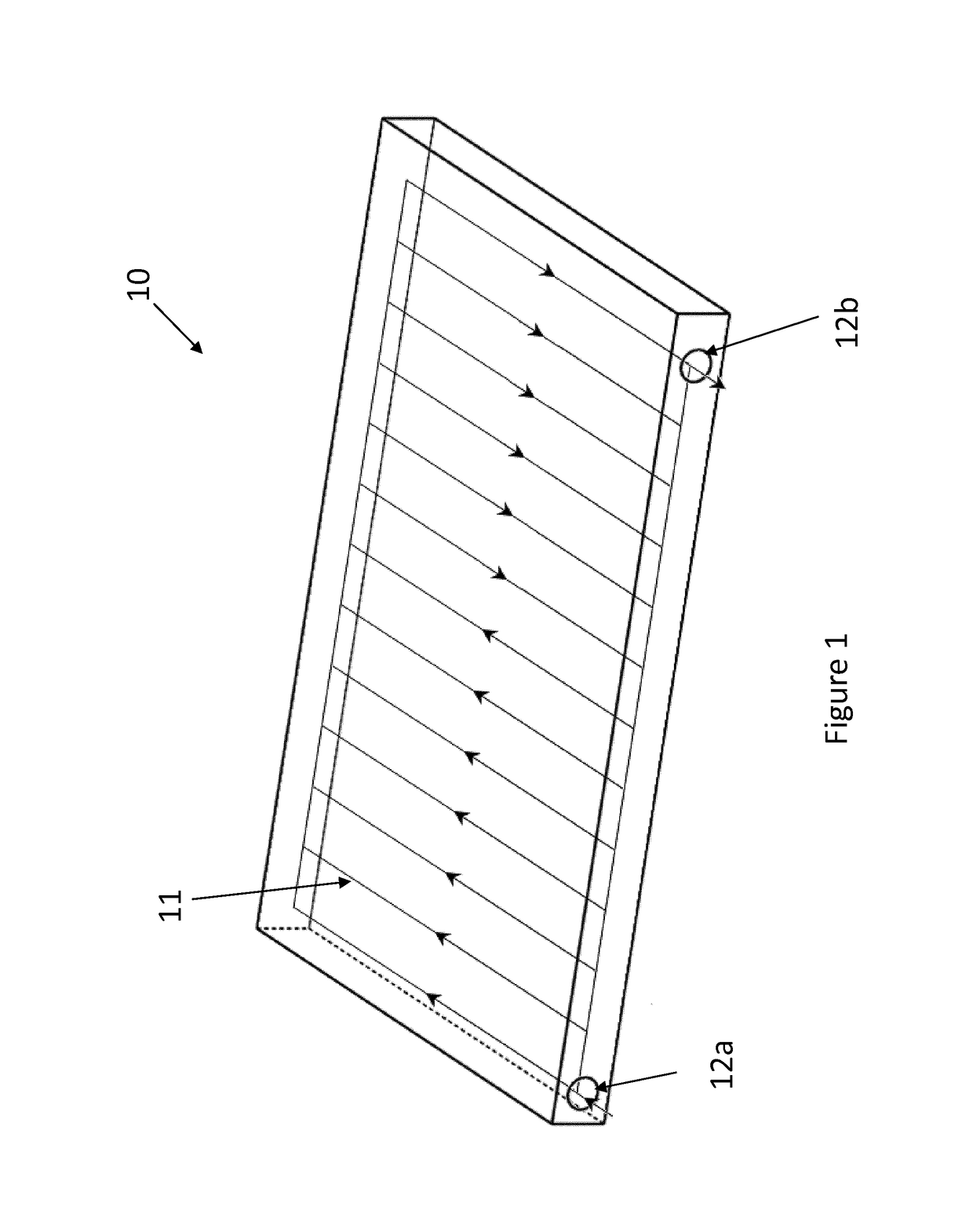
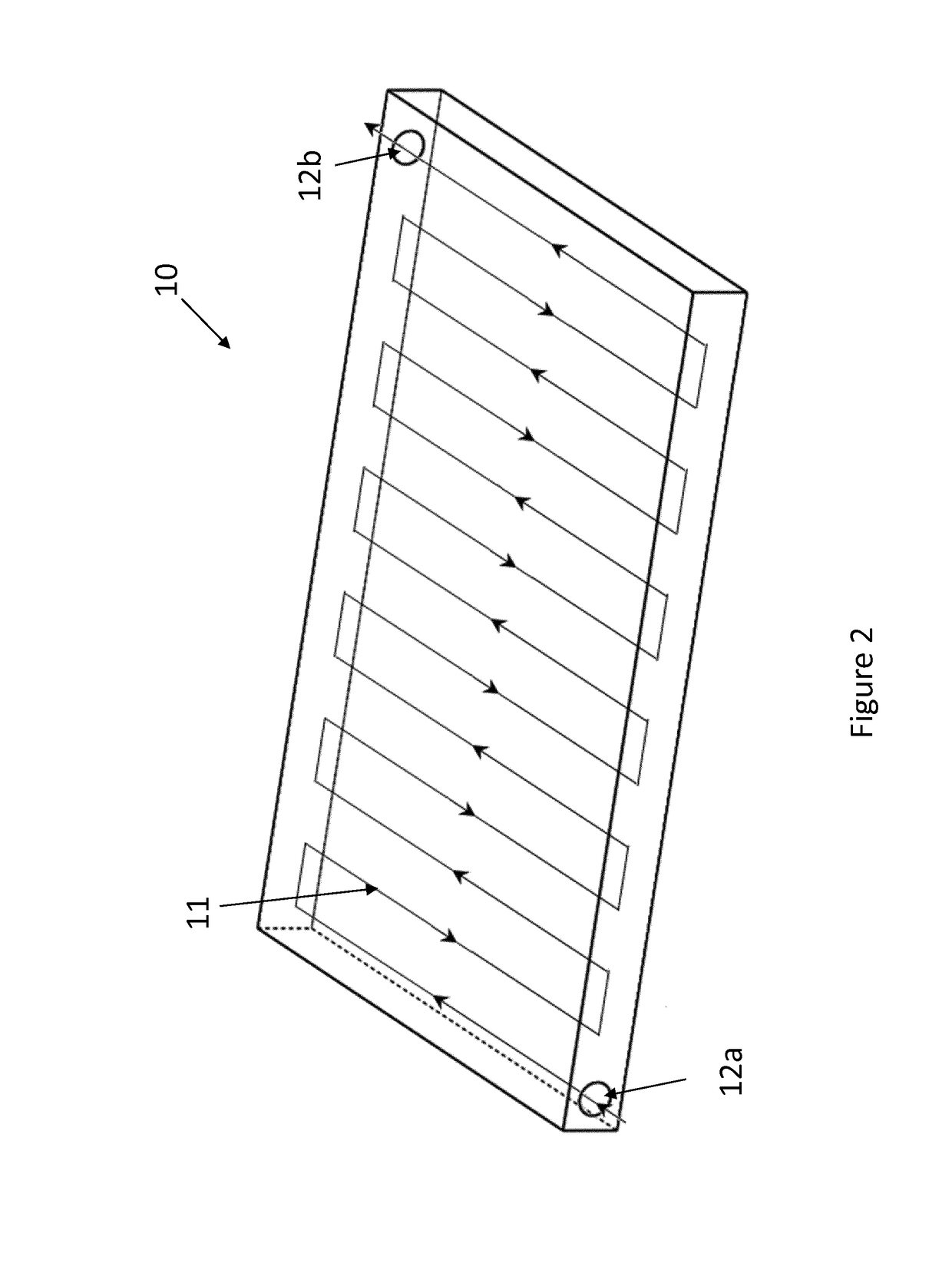
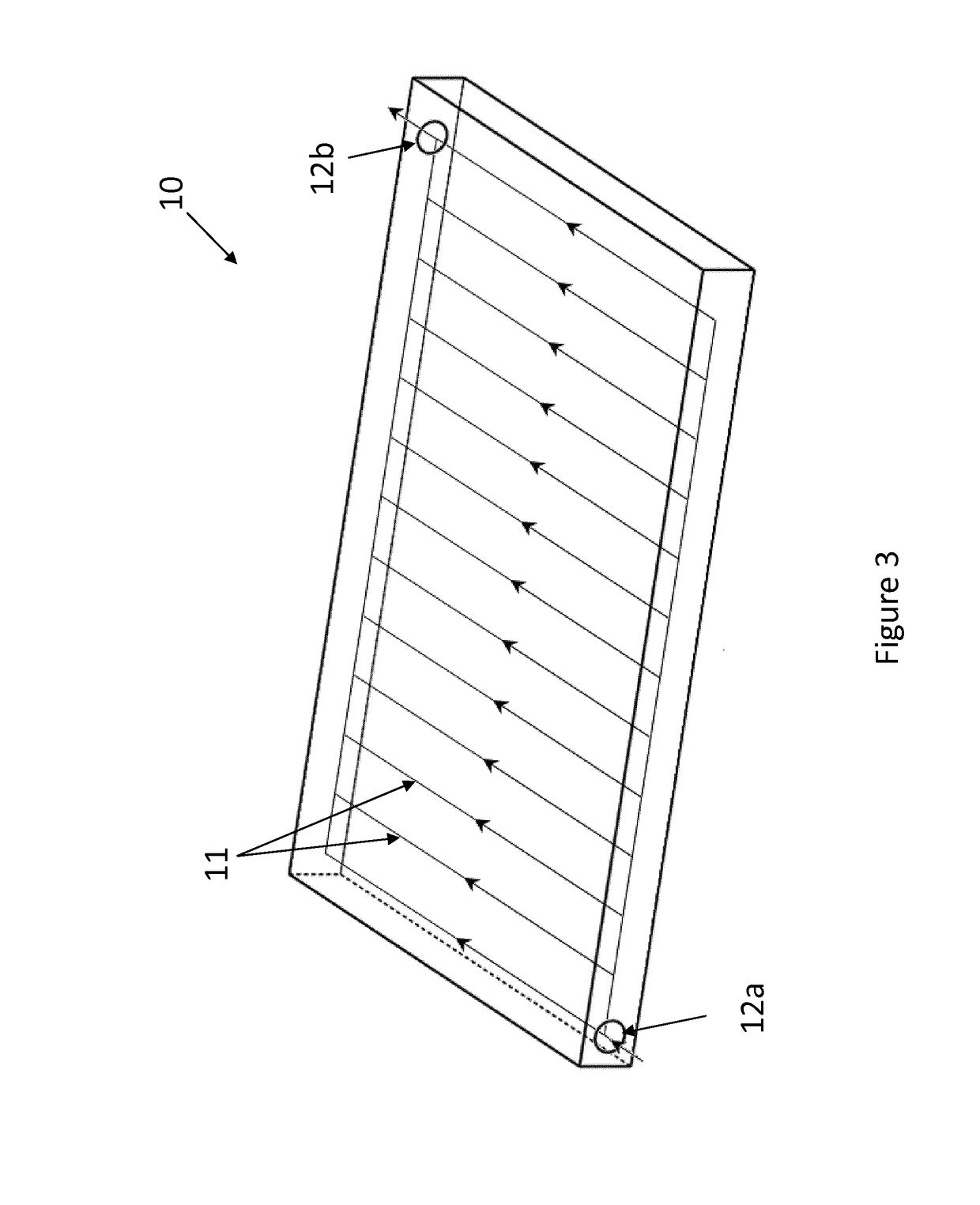
[0052]The present invention will be described with respect to particular embodiments and with reference to certain drawings but the invention is not limited thereto but only by the claims. The drawings described are only schematic and are non-limiting. In the drawings, the size of some of the elements may be exaggerated and not drawn on scale for illustrative purposes. The dimensions and the relative dimensions do not necessarily correspond to actual reductions to practice of the invention.

[0053]Furthermore, the terms first, second, third and the like in the description and in the claims, are used for distinguishing between similar elements and not necessarily for describing a sequential or chronological order. The terms are interchangeable under appropriate circumstances and the embodiments of the invention can operate in other sequences than described or illustrated herein.

[0054]Moreover, the terms top, bottom, over, under and the like in the description and the claims are used fo...


PUM


Abstract

Passive thermal storage systems and methods comprising at least one thermal storage module for storing thermal energy in a predetermined temperature range, are disclosed. The thermal storage module comprises an FT unit and a Heat Storage (HS) unit at least partially filled with a first Phase Change Material (PCM). The HS unit comprises a container. The thermal storage module may be in the form of a stacked structure comprising the FT unit having a first wall with a first heat exchange surface and the HS unit having a second wall with a second heat exchange surface, the first and second heat exchange surfaces being in thermal contact with each other. The thermal storage system may be used to maintain the temperature of the payload of a temperature controlled container at a predetermined value or within a predetermined range.

Description

TECHNICAL FIELD[0001]The present invention relates to a thermal storage system arranged for storing thermal energy, which is for example suitable for maintaining a payload space at a predetermined temperature. The present invention further relates to a temperature controlled container comprising a thermal storage system according to the present invention.BACKGROUND ART[0002]Phase change materials (PCM) are substances that absorb and release thermal energy during the phase change. When a PCM freezes, it releases a large amount of energy in the form of latent heat at a relatively constant temperature. Conversely, when such material melts, it absorbs a large amount of heat for instance from the environment. As thermal energy carrier, PCMs are ideal for a variety of everyday applications that require temperature control. The most commonly used PCM is water / ice. Ice is an excellent PCM for maintaining temperatures at 0° C. But water's freezing point is fixed at about 0° C. (32° F.), whic...

Claims


Application Information

Patent Timeline
Patent Type & Authority Applications(United States)
IPC IPC(8): F28D20/02F25D3/00
CPCF28D20/021F28D20/02F28D20/026F25D3/005F28D2020/0013B60H1/005B60H1/3232F24H7/02F24D2220/10F28F2255/16F25D3/00Y02E60/14
Inventor CANIERE, HUGOCOUSAERT, ERIKHUISSEUNE, HENK
Owner UNIV GENT
Why Eureka
Try Eureka