Multi-laser gas leakage detector

a gas leakage detector and multi-laser technology, applied in the direction of instruments, fluid tightness measurement, structural/machine measurement, etc., can solve the problems of aging gas delivery infrastructure, inconvenient operation, and inability to detect gas leakage,

Active Publication Date: 2019-01-03
AURORA INNOVATIVE TECH LLC
View PDF6 Cites 29 Cited by
  • Summary
  • Abstract
  • Description
  • Claims
  • Application Information

AI Technical Summary

Problems solved by technology

However, at the same time, gas delivery infrastructure is aging.
However,

Method used


Image

  • Multi-laser gas leakage detector
  • Multi-laser gas leakage detector
  • Multi-laser gas leakage detector

Examples


first example

II.A First Example Method

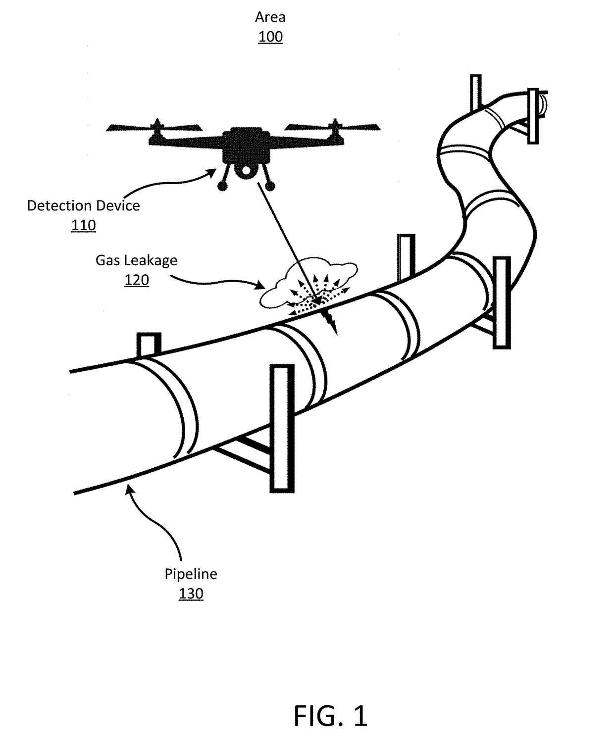
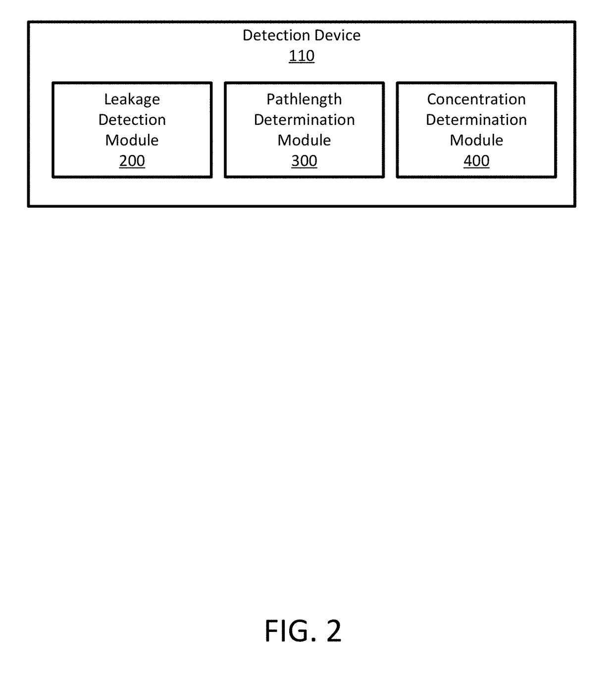
[0043]FIG. 4A is a flow chart illustrating an example method 400A for detecting a gas leakage 120 using multiple light beams. The detection device 110 identifies 410 a region of a pipeline 130 in the area 100 to inspect for a gas leakage 120. The detection device 110 inspects a region of the pipeline at a particular time point as it traverses along the pipeline. A dimension of a region inspected at a time point can be predetermined by a user or determined by the detection device 110 according to the ambient environment. The regions are selected such that there is no gap between any two consecutive regions such that the detection device 110 can inspect the pipeline 130 entirely or substantially entirely within the area 100.

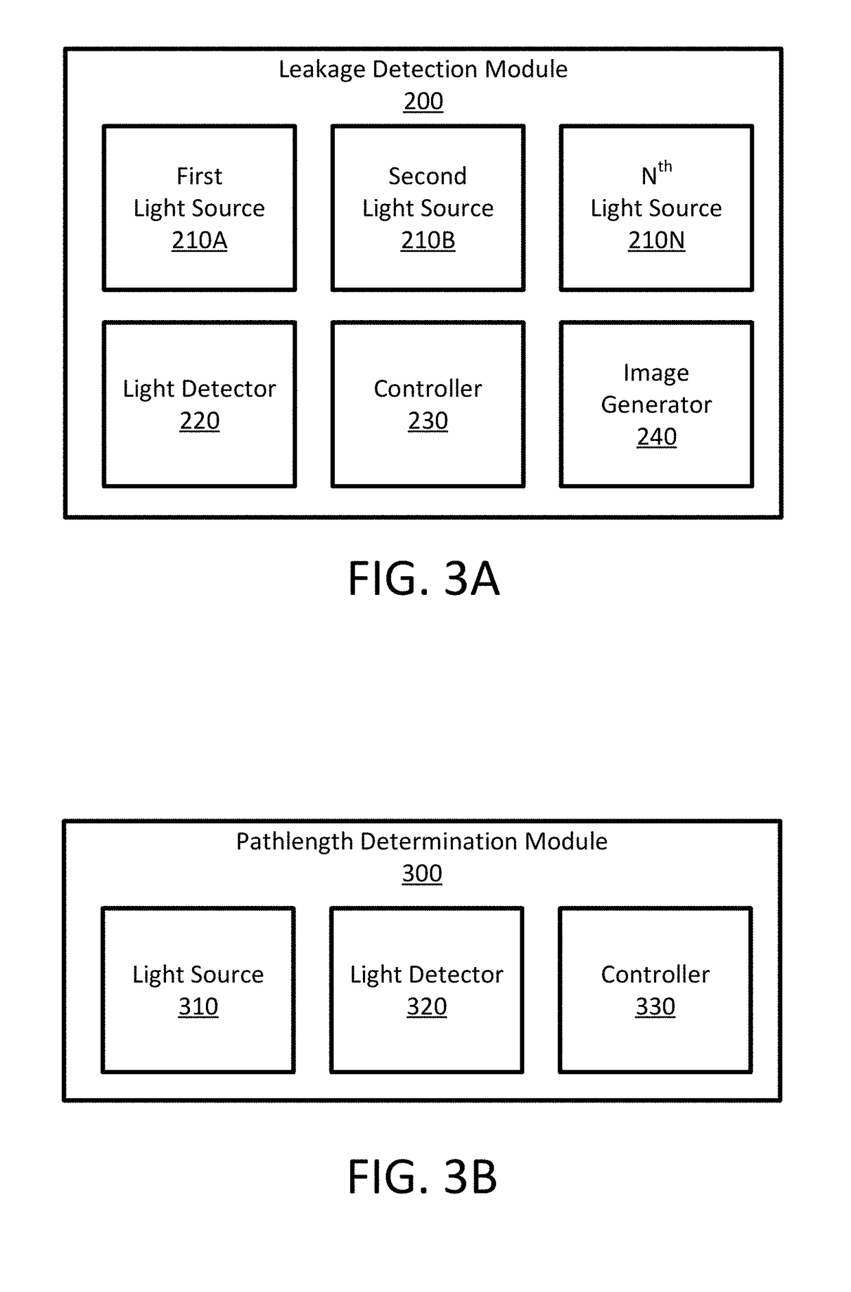
[0044]The detection device 110 emits 412 a first light beam towards the region of the pipeline 130. The first light beam has a wavelength that is in the mid-IR range. The wavelength can be predetermined or determined based on a gas that mig...

second example

II.B Second Example Method

[0053]FIG. 4B is a flow chart illustrating an example method 400B of detecting a gas leakage 120 using multiple light beams. The detection device 110 identifies 440 a region of a pipeline 130 to inspect for a gas leakage 120. Similar to method 400A, the detection device 110 selects dimension of the region such that there are no gap between any two consecutive regions such that as the detection device 110 traverses the pipeline 130.

[0054]The detection device 110 emits 442 a first light beam towards the region using a first light source. The first light beam has a first wavelength that is in the mid-IR range. The detection device 110 emits 444 a second light beam towards the region using a second light source. The second light beam has a second wavelength that is in the mid-IR range. The first and second wavelength can be predetermined or determined based on a particular gas that may be in a gas leakage 120.

[0055]The detection device 110 modulates 446 the fir...

third example

II.C Third Example

[0060]FIG. 4C is a flow chart illustrating an example method 400C of detecting a gas leakage 120 using multiple light beams. The detection device 110 identifies 460 a region of a pipeline 130 to inspect for a gas leakage 120. Similar to method 400A, the detection device 110 selects a dimension of the region such that there are no gap between any two consecutive regions such that as the detection device 110 traverses the pipeline 130.

[0061]The detection device 110 emits 462 a light beam towards the region of the pipeline 130. The light beam has a wavelength that is in the mid-IR range. The wavelength can be predetermined or determined based on a gas that might be included in a gas leakage 120. In some embodiments, the detection device 110 emits multiple light beams along different directions towards the region either concurrently or sequentially.

[0062]The detection device collects 464 a first reflected light beam which is the light beam emitted by the detection devi...


PUM


Abstract

A system remotely detects a gas leakage from a pipeline in an area. The system detects a gas leakage by determining an absorption or emission of gasses in the area. The gas detection system includes at least two light sources. The lasers can include lasers for detecting absorbance of gasses in the area, lasers for stimulating emission of gasses in the area, and lasers for detecting a pathlength. Absorption is determined based on the relative amplitude difference of emitted and reflected light beams. Emission is determined based on an amount emission stimulated by absorbed lasers. Pathlength is determined calculating time of flight of a light beam. The detection system calculates a concentration of the gasses in the area using the determined absorption and pathlength. The detection system can also generate an image representing a gas leakage in the area. The detection system may be attached to an unmanned aerial vehicle.

Description

CROSS REFERENCE TO RELATED APPLICATIONS[0001]This application is a continuation in part application of and claims the benefit of priority to U.S. application Ser. No. 15 / 678,052, filed Aug. 15, 2017, and also claims the benefit of priority to U.S. Provisional Application No. 62 / 527,784, filed Jun. 30, 2017, each of which is incorporated herein by reference in its entirety for all purposes.BACKGROUND OF THE INVENTION1. Field of the Invention[0002]This description relates generally to detection of gas leakage, and more specifically detection of gas leakage using mid-infrared laser.2. Description of the Related Art[0003]Natural gas consumption in the U.S. is expected to increase rapidly. However, at the same time, gas delivery infrastructure is aging. Accordingly, reliable and timely detection of natural gas leakage is critical to ensure the gas delivery infrastructure's reliability. Conventional non-optical methods that detect natural gas leakage are based on various mechanisms such a...

Claims


Application Information

Patent Timeline
IPC IPC(8): G01M3/38
CPCG01N21/35G01M3/38G01M3/00G01N2021/1795G01N2021/3513G01N2021/399G01N21/3504G01N2021/1793G01M3/2807B64C39/024B64U2101/30G01N33/0027
Inventor LI, JIEBOGUO, XUNMINZHAO, WANYIYIN, ZHENYUAN, CHUHAN
Owner AURORA INNOVATIVE TECH LLC
Why Eureka
Try Eureka