Motion preserving spinal total disc replacement apparatus, method and related systems

Active Publication Date: 2019-01-10
DOTY KEITH L
View PDF11 Cites 6 Cited by
  • Summary
  • Abstract
  • Description
  • Claims
  • Application Information

AI Technical Summary

Benefits of technology

[0008]The cushion rings introduced in D3 interact with the Ring-Joint-Stop (RJS) to protect the RJS and retainer plate from impingement damage that would be caused by rotations exceeding their Range-of-Motion (ROM). As soon as the RJS c...

Problems solved by technology

Rotations outside of the normal ...

Method used


Image

  • Motion preserving spinal total disc replacement apparatus, method and related systems
  • Motion preserving spinal total disc replacement apparatus, method and related systems
  • Motion preserving spinal total disc replacement apparatus, method and related systems

Examples


example 1

[0126]Load And Deformation Considerations for the NFS-1 Device According to This Invention When Implanted Into a Living Recipient as a Motion Preserving Replacement of a Defective Intervertebral Disc

[0127]For purposes of exemplification, the area of the spherical section of the nucleus in a preferred embodiment is defined as about 48.66 mm2. Assuming a force F=486.6 N is exerted at the top endplate, such force is distributed across the spherical section concavity present in the underside of the top endplate, since at such load, where a titanium endplate is utilized, the top endplate remains substantially rigid. Accordingly, the pressure experienced by the Nucleus is: 486.6 N / 48. 66 mm2=10 MPa. At 10 MPa, depending on the composition of the nucleus, a compression of about 10% is experienced. The height of the nucleus, from the top of the bottom endplate to the top of the top endplate spherical concavity is preferably about 4.8 mm. Thus, a 10% compression causes the height of the nucl...

example 2

[0131]Surface Area and Load Considerations for the NFS-1 Device According to This Invention When Implanted Into a Living Recipient as a Motion Preserving Replacement of a Defective Intervertebral Disc

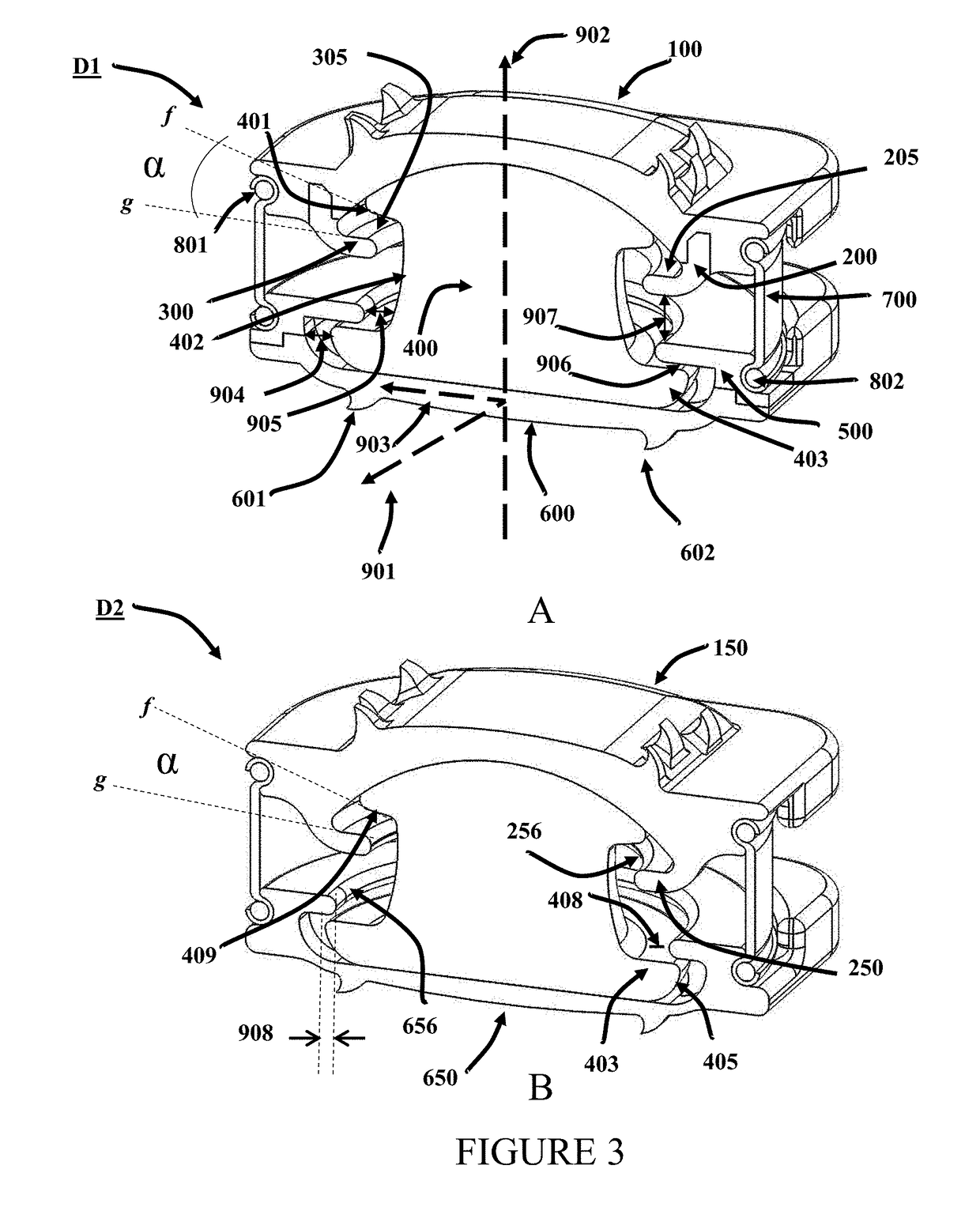
[0132]In a preferred embodiment, the surface area of the dome of the nucleus is about 50 mm2. In such an embodiment, a 500N load, approximately 3.3 times maximum cervical spinal loading of 150N and 10 times the load of the human head (˜5 Kg), produces a stress of about 10 MPa on the dome surface and will compress a particular 6 mm PCU candidate only 10% or 0.6 mm in the neutral position. A gap 907 of about 1 mm is expected to protect against impingement of the RJS 200 or 300 with the retainer 500 except in extreme circumstances Similar claims apply to RJS 1200 and RJS 1400. According to Moroney et al (J. Biomechanics, 21(9): 767,1988) the stiffness coefficient of a cervical disc is 500N / mm. Thus, a disc compression of only about 1 mm is anticipated to result from a load of 500N.

example 3

[0133]Range of Motion and Gaps Provided in the NFS-1 Device to Accommodate Such Motions

[0134]In an exemplary embodiment according to this invention, the motion of the top endplate, riding on the nucleus spherical section is defined by the ring-joint-stop raceway, which can allow rotations up to approximately ten degrees (10°) about any axis at the center-of-rotation and perpendicular to the central axis of the nucleus. Furthermore, in a preferred embodiment, the distance between the top and bottom plate at any extremal rotation, permitted in relation to each other, is slightly larger than about 0.4 mm. The 0.4 mm is a consequence of specific geometry of one embodiment of the device according to this invention. Those skilled in the art will appreciate that while 0.4 mm is mentioned here as a specific value of the gap between any portion of the top plate and any portion of the bottom plate, for particular subjects, and depending on the particular level at which intervertebral disc rep...


PUM

PropertyMeasurementUnit
Thicknessaaaaaaaaaa
Forceaaaaaaaaaa
Diameteraaaaaaaaaa

Abstract

The present invention provides a next generation, closed profile, total disc replacement device with mechanical features designed to sustain, restrain and guide the larger motions required to preserve normal mechanical motion, while at the same time, providing a flexion component to guide and restrain the finer motions reached at the extremes of the mechanical motion preservation components.

Description

FIELD OF THE INVENTION[0001]Motion preserving total spinal disc replacement devices, methods and systems.BACKGROUND OF THE INVENTION[0002]When a biological disc between adjacent spinal vertebrae fails, pain, reduced flexibility, reduced motion, and other adverse effects result. To date, there have been efforts to address such biological failures, particularly in the cervical and lumbar regions of the spine, by a variety of techniques ranging from non-invasive, palliative approaches, to removal of the disc and fusion of the adjacent vertebral bodies to each other. More recently, a series of non-fusion Total Disc Replacement (TDR) technologies have been developed wherein one form or another of a motion preserving TDR device is inserted between the adjacent vertebrae, with the almost diametrically opposing objectives of (a) providing spinal stability while (b) preserving motion at the affected spinal disc and vertebral segments.[0003]Thorough reviews of this art area are provided, for ...

Claims


Application Information

Patent Timeline
IPC IPC(8): A61F2/44
CPCA61F2/4425A61F2/441A61F2002/443A61F2002/444A61F2002/30528A61F2002/30112A61F2002/30662A61F2002/30235A61F2002/30299A61F2002/30474A61F2002/30495A61F2002/305A61F2002/30563A61F2002/30649A61F2002/30841A61F2002/30985
Inventor DOTY, KEITH L
Owner DOTY KEITH L
Why Eureka
Try Eureka