Eureka AIR delivers breakthrough ideas for toughest innovation challenges, trusted by R&D personnel around the world.

Oil Tanker

a technology for oil tankers and oil tanks, applied in waterborne vessels, passenger handling devices, ship accessories, etc., can solve the problems of obstructing the effective use, requiring a large amount of money for maintenance and inspection work, and easy corrosion, so as to reduce marine pollution, facilitate crew passage, and use the effect of the upper area

Inactive Publication Date: 2019-01-10
MORIMOTO NOBUYOSHI
View PDF1 Cites 2 Cited by
  • Summary
  • Abstract
  • Description
  • Claims
  • Application Information

AI Technical Summary

Benefits of technology

The present invention allows for the elimination of the cargo oil delivery pipe, reducing marine pollution and making better use of the oil tanker's deck area. It also makes it easier for a crew to pass through.

Problems solved by technology

In this type of piping, the cargo oil delivery pipe 50 laid on the upper deck has a weak point in safety in terms of marine pollution of a leak accident from a cargo oil pipe and easily corrodes when exposed to waves and sea breeze and requires a large amount of money for a maintenance and inspection work.
In addition, the cargo oil delivery pipe 50 laid on the upper deck is laid near the central portion of the upper deck, so that the cargo oil delivery pipe 50 obstructs the effective use of the huge upper deck and a passage of a crew and a working car in the left and right direction on the upper deck and reduces the work efficiency of a crew.
However, it is not only the cargo oil delivery pipe that obstructs the passage on the upper deck in the conventional oil tanker.
This also presents the same problem.
In particular, a dual-purpose oil tanker capable of carrying ore and bulk has a hatchway provided in an upper deck and hence presents a more problem for passage on the upper deck.
In addition, when ore and coal are loaded, the core and the coal drop on the pipes, which presents also problems such that the pipes need to be covered with a protection cover and that a lot of time is required to remove the dropped ore and coal piled under the protective cover after loading the ore and the coal.
In a case where a cargo oil delivery pipe is broken by an accident of a cargo oil pipe, there is a possibility that marine pollution will be caused.

Method used


Image

  • Oil Tanker
  • Oil Tanker
  • Oil Tanker

Examples


Embodiment Construction

[0019]Hereinafter, embodiments of the present invention will be described with reference to the drawings.

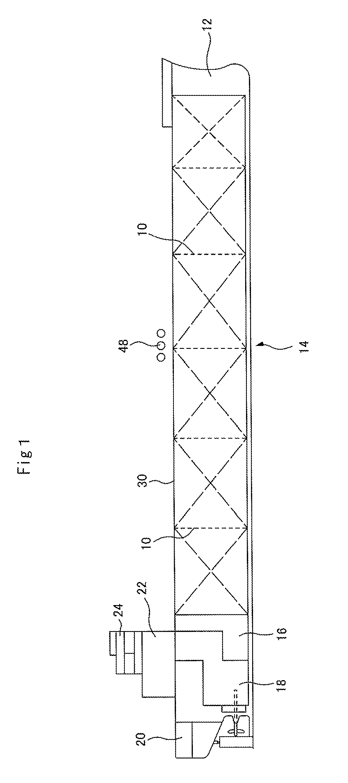
[0020]First, a dedicated oil tanker carrying only crude oil will be described. As shown in FIG. 1 and FIG. 2, a hull is partitioned by transverse bulkheads 10 and a bow portion 12, a cargo tank area 14, a pump room 16, an engine room 18, and a stern portion 20 are arranged in this order. An accommodation area 22 and a wheelhouse 24 are located above the engine room 18.

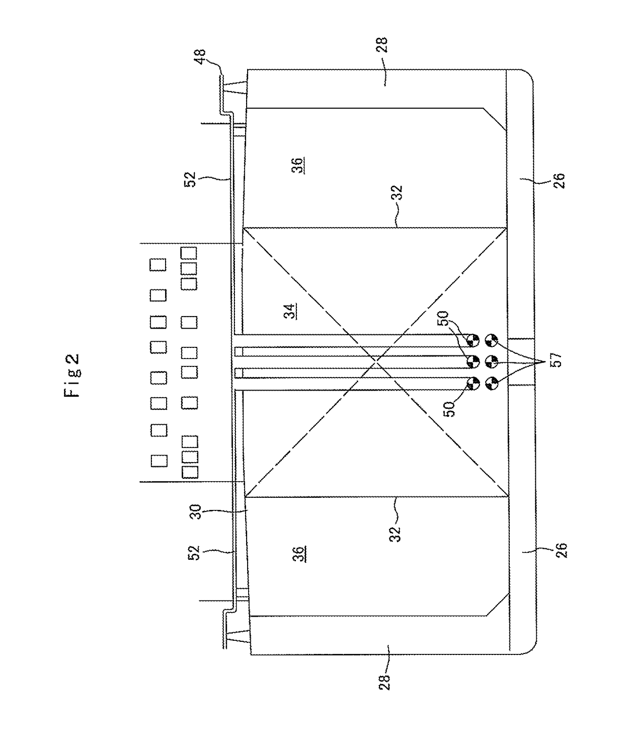
[0021]The cargo tank area 14, as shown in FIG. 2, has both of the bottom and the side of the ship constructed of a double hull structure and their interiors are constructed of ballast tanks 26, 28, respectively. A space surrounded by the double hull structure and an upper deck 30 is partitioned into a center cargo tank 34 and left and right cargo tanks 36 by longitudinal bulkheads 32 extended longitudinally on the left and right sides.

[0022]According to the present invention, there is provided a cargo oil delivery p...


PUM


Abstract

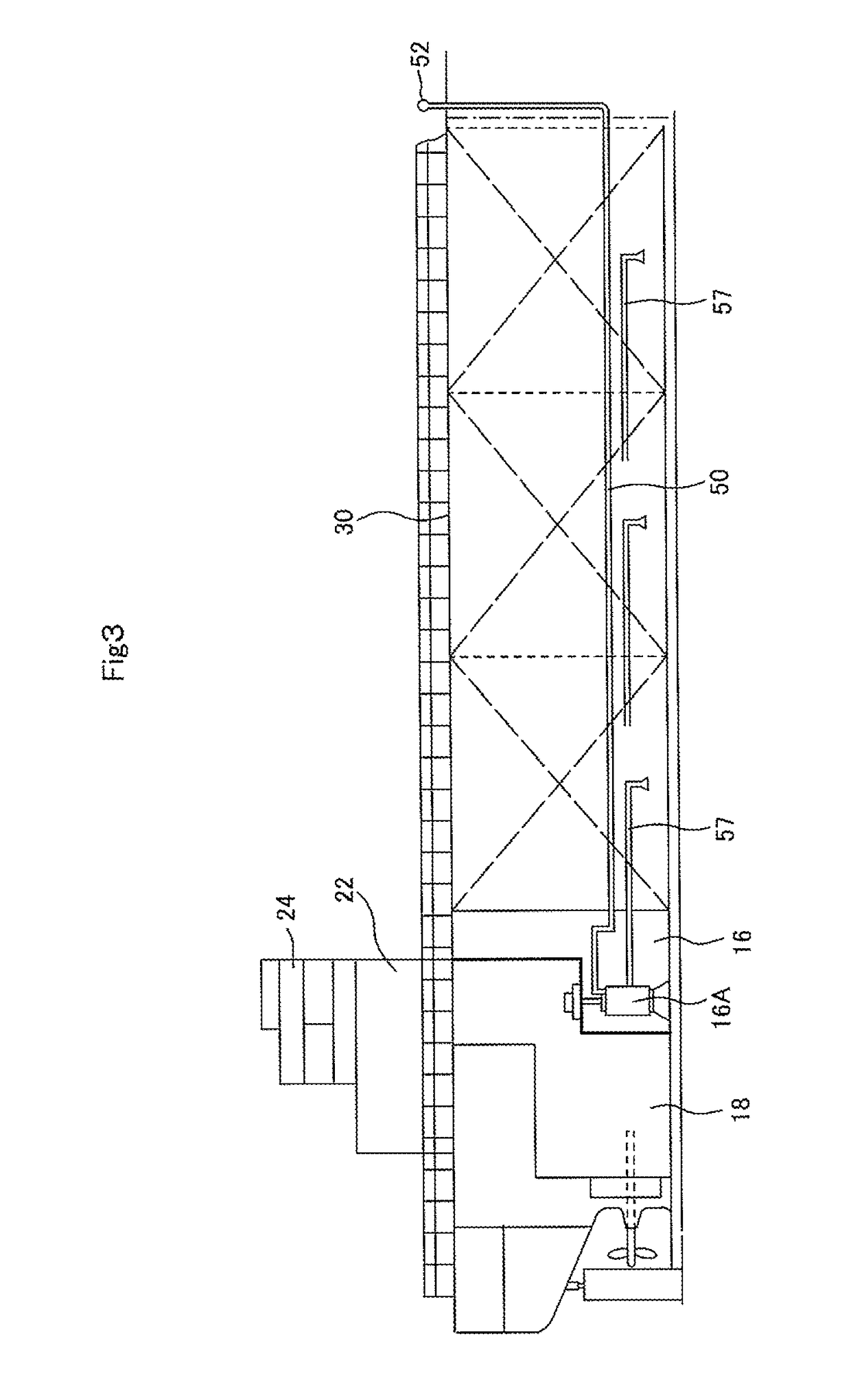
An oil tanker is provided with a cargo oil delivery pipe for connecting a cargo oil pump in a pump room arranged in front of an engine room in a rear portion of a hull to a shore connection provided nearly in a central portion on the upper deck of the hull, and a cargo suction pipe for connecting the cargo oil pump to a cargo oil tank. The cargo oil delivery pipe is passed through a cargo tank area below the upper deck of the hull and is extended forward from the pump room and is passed through the upper deck and is connected to a cross pipe and is coupled to the shore connection.

Description

TECHNICAL FIELD[0001]The present invention relates to an oil tanker, that is, a dedicated oil tanker carrying only crude oil, and a dual-purpose oil tanker carrying not only crude oil but also solid cargo such as ore and coal, and in particular, to an oil tanker having a cargo oil pipe and other piping structure.BACKGROUND ART[0002]In an oil tanker, as shown in FIG. 9, a cargo oil pump 17 is arranged in a pump room 16 provided in front of an engine room 18 in a stern, and a cargo oil suction pipe 57, which communicates with each cargo tank, and a cargo oil delivery pipe 50, which is connected to a shore connection 48 provided on an upper deck in the central portion of a hull, are connected to the cargo oil pump 17, respectively. When oil (crude oil) is unloaded, oil in each cargo oil tank is sucked by the cargo oil pump 17 through the cargo oil suction pipe 57 and then is sent to the shore connection 48 through the cargo oil delivery pipe 50 and is sent out of the shore connection 4...

Claims


Application Information

Patent Timeline
Patent Type & Authority Applications(United States)
IPC IPC(8): B63B25/08B63B27/25
CPCB63B25/082B63B27/25
Inventor MORIMOTO, NOBUYOSHI
Owner MORIMOTO NOBUYOSHI
Why Eureka
Eureka Blog
Learn More