Spring return throttle actuator, method of control thereof and throttle assembly

a technology of spring return and actuator, which is applied in the direction of electronic commutators, machines/engines, stopping arrangements, etc., can solve the problems of difficult cooling of the components involved, increased difficulty in obtaining the desired working life, and increased heat generation of the electrically driven actuator. achieve the effect of increasing measurement accuracy

Inactive Publication Date: 2019-01-10
SCANIA CV AB
View PDF3 Cites 0 Cited by
  • Summary
  • Abstract
  • Description
  • Claims
  • Application Information

AI Technical Summary

Benefits of technology

[0019]This is highly advantageous since the electric motor and the control electronics will be subjected to less current supply which is a positive factor i.e. for the working life of these elements.
[0020]Furthermore, the energy required for the electric motor and the control electronics will be reduced which is a positive factor for temperature reduction and also for fuel consumption.
[0022]The control unit preferably includes a bridge circuit having one branch connected to each one of the coils. This circuitry makes the actuator easily controlled in an economic and logical manner. This advantage is even more enhanced when each branch includes a transistor switch connected to each one of the coils.
[0023]At least one movement sensor is preferably positioned to detect DC motor rotor movements in order to guarantee stability and maintained settings and adjustability. In particular it is advantageous when a plurality of Hall sensors is positioned to detect DC motor rotor movements, the Hall sensors of said plurality being distributed around the rotor to increase measurement accuracy. The sensors can also be positioned such that they detect the position of the throttle itself or an element of the transmission, since the position of the motor can be derived therefrom.
[0030]DC motor rotor movements are preferably detected by at least one movement sensor and more preferred by a plurality of Hall sensors being rotationally distributed to increase measurement accuracy.

Problems solved by technology

One problem with this previously known solution is that heat is generated in respect of the electrically driven actuator and that the components involved are difficult to cool, in particular in diesel engines where the environment around the actuator suffers from heat generated by the diesel engine itself.
Unfortunately, high temperatures in the control electronics makes it more difficult to obtain desired working life.

Method used


Image

  • Spring return throttle actuator, method of control thereof and throttle assembly

Examples


Embodiment Construction

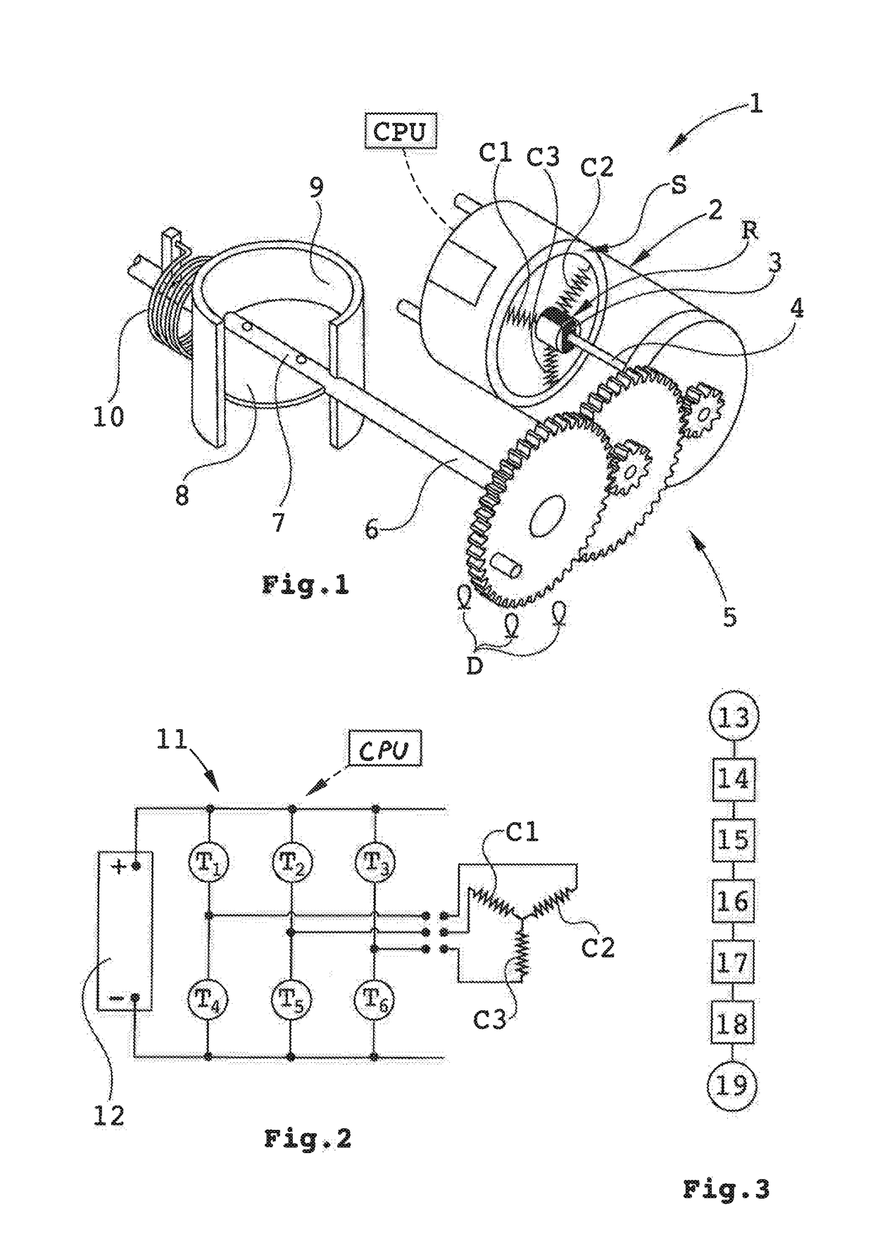
[0037]FIG. 1, shows a throttle assembly whereof a spring return throttle actuator is generally depicted with reference number 1. The actuator 1 includes a DC motor 2 having three coils C1, C2 and C3 in its stator S. The rotor R is as usual provided with a permanent rotor magnet 3 and an output shaft 4.

[0038]A gear transmission 5 is connected to the output shaft 4 and an outgoing shaft 6 from the gear transmission 5 is coupled with its distal end to a throttle shaft 7 of a throttle 8. The actuator has a movement range between closed throttle and fully opened throttle.

[0039]It should be noted that the motor also could be directly connected to the throttle.

[0040]The throttle 8 is arranged in a channel 9 to control a gas stream flowing through the channel 9.

[0041]A throttle return spring 10 is positioned around the outgoing shaft 6 and functions to provide a spring torque urging the outgoing shaft 6 to rotate towards a “normal” position of the throttle 8 which may be fully open or fully...


PUM


Abstract

A spring return throttle actuator including: an electric, plural-coil DC motor having an output shaft, a throttle return spring, a gear transmission connected to the output shaft, a control unit adapted to control power supply to the DC motor, wherein the spring return throttle actuator has a movement range between closed throttle and opened throttle. The control unit is arranged to short-circuit at least two DC motor coils in order to create a DC motor return resist torque, and the return spring is balanced such that generated spring return torque over the whole movement range of the actuator does not exceed said DC motor return resist torque. The invention also relates to a method and a throttle assembly.

Description

CROSS-REFERENCE TO RELATED APPLICATION(S)[0001]This application is a National Stage Application (filed under 35 § U.S.C. 371) of PCT / SE2016 / 051247, filed Dec. 12, 2016 of the same title, which, in turn claims priority to Swedish Application No. 1650012-6 filed Jan. 5, 2016 of the same title; the contents of each of which are hereby incorporated by reference.FIELD OF THE INVENTION[0002]The invention relates to a spring return throttle actuator including: an electric, plural-coil, DC motor having an output shaft, a throttle return spring, a gear transmission connected to the output shaft, a control unit adapted to control power supply to the DC motor, wherein the actuator has a movement range between closed throttle and opened throttle. The invention also relates to a method for control thereof and a throttle assembly.BACKGROUND OF THE INVENTION[0003]Throttle assemblies are employed to control gas streams in respect of vehicle engines. The electric motor of the actuator is typically s...

Claims


Application Information

Patent Timeline
Patent Type & Authority Applications(United States)
IPC IPC(8): F16K31/04F02D9/10H02P3/12H02P6/08H02P6/17H02P6/24
CPCH02P6/24H02P6/085H02P6/17H02P3/12F16K31/046F02D9/105F02D9/1065F02D11/10F02D11/106F02D11/107F16K1/221F16K31/042F02D2009/0213F02D2011/102H02P7/00
Inventor STR T, FREDRIKZAMANI, SEBASTIAN
Owner SCANIA CV AB
Why Eureka
Try Eureka