
Electronic device

a technology of electronic devices and shielding materials, applied in earth/grounding circuits, shielding materials, electrical devices, etc., can solve the problems of noise coupling to another line within the shield, preventing the efficient discharge of radiated electromagnetic waves, etc., and achieve the effect of effective grounding

Inactive Publication Date: 2019-01-10
LG ELECTRONICS INC
View PDF11 Cites 11 Cited by
  • Summary
  • Abstract
  • Description
  • Claims
  • Application Information

AI Technical Summary

Benefits of technology

The invention provides an electronic device with a slim shield can that effectively blocks electromagnetic waves. This prevents interference and improves performance. Even when the shield can is made thinner, the current is still dispersed and can be effectively grounded. This enables the device to generate high-frequency waves while reducing interference, resulting in improved performance and reliability.

Problems solved by technology

However, when the thickness of the shield can is reduced, the electromagnetic waves reach only a specific region adjacent to the shield can, and accordingly a region where a current flows is limited to the specific region.
Further, when a high frequency signal having a straight-running property flows due to the electronic components, the current induced by the electromagnetic waves reaches only a near partial region of the shield can, which may prevent the radiated electromagnetic waves from efficiently being discharged to the ground, or cause noise to be coupled to another line within the shield can.
Or, when the induced current fails to be transferred to the ground through the shield can, a problem arises that the shield can structure itself becomes an Electro Magnetic Interference (EMI) radiator.

Method used


Image

  • Electronic device
  • Electronic device
  • Electronic device

Examples


Embodiment Construction

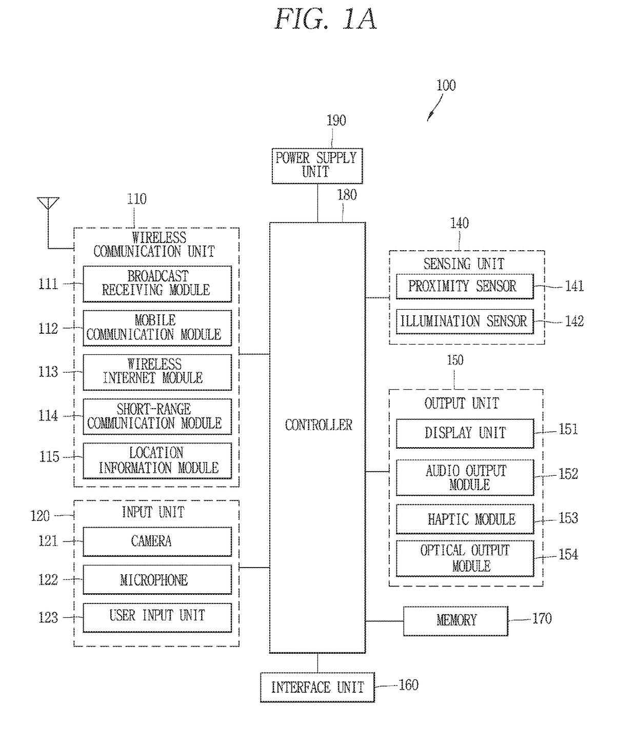
[0029]FIG. 1A is a block diagram of a mobile terminal in accordance with the present disclosure.

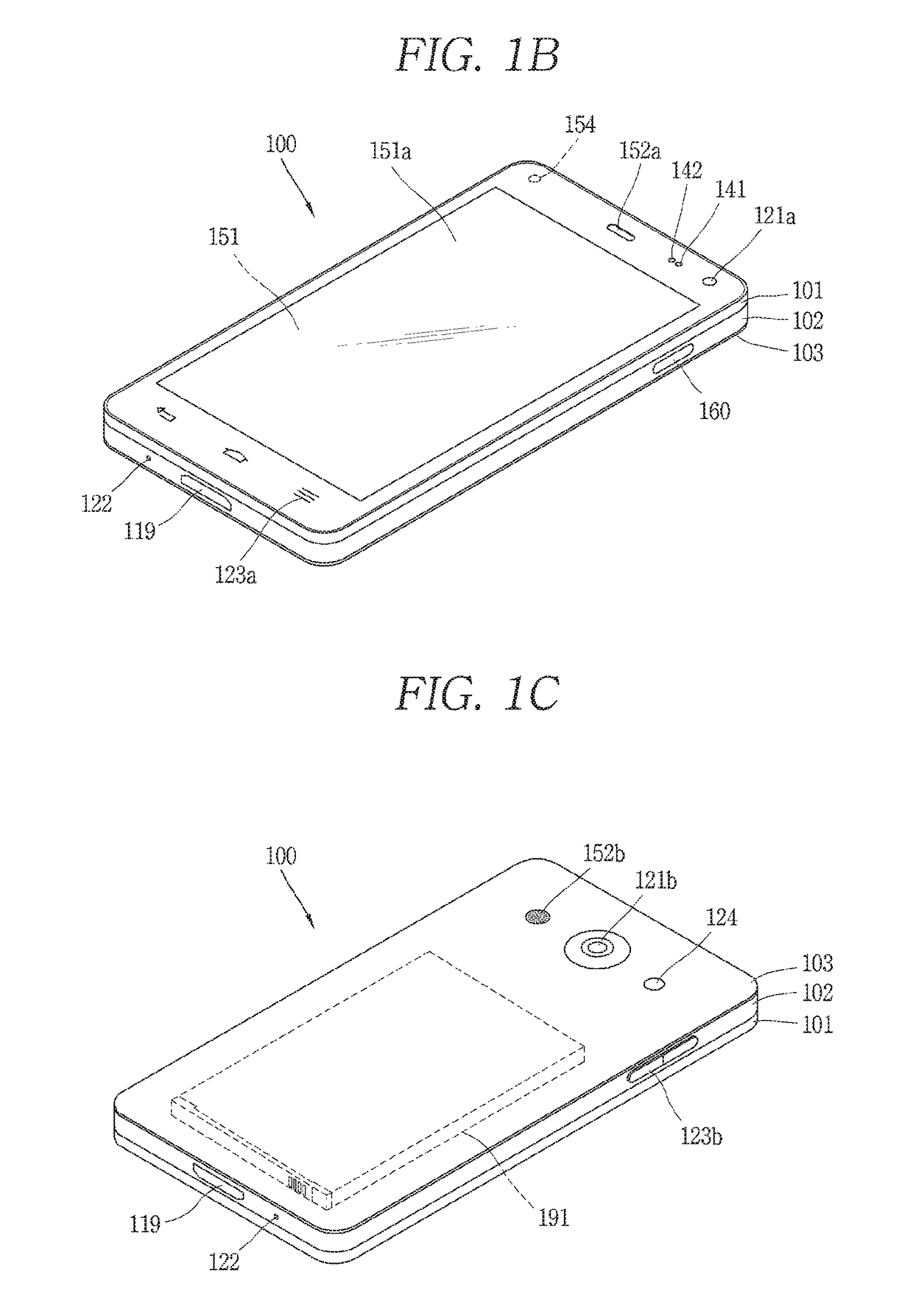
[0030]The mobile terminal 100 may be shown having components such as a wireless communication unit 110, an input unit 120, a sensing unit 140, an output unit 150, an interface unit 160, a memory 170, a controller 180, and a power supply unit 190. FIG. 1 shows the electronic device 100 having various components, but it may be understood that implementing all of the illustrated components is not a requirement. Greater or fewer components may alternatively be implemented.

[0031]In more detail, among others, the wireless communication unit 110 may typically include one or more modules which permit communications such as wireless communications between the electronic device 100 and a wireless communication system, communications between the electronic device 100 and another mobile terminal, or communications between the electronic device 100 and an external server. Further, the wireless communi...


PUM


Abstract

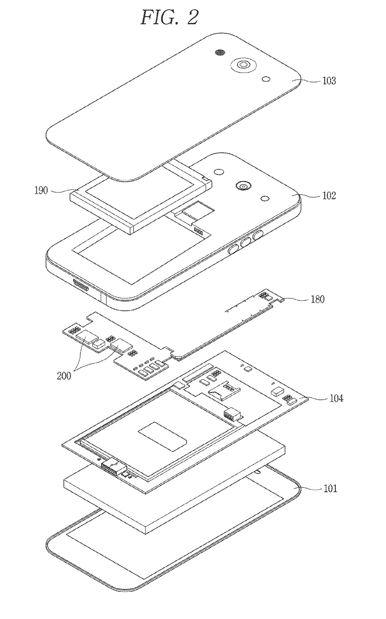
The present invention relates to an electronic device, including a body including an inner frame, a circuit board disposed inside the body to transmit a signal, an electronic component disposed on the circuit board, and a shield can disposed between the circuit board and the inner frame, and covering the electronic component such that a current induced from the electronic component flows toward the circuit board, wherein the shield can includes a base portion including a first region fixed to the circuit board, and a second region covering the electronic component, and at least one magnet portion overlapping the second region of the base portion, and forming a magnetic field in a direction from inside to outside of the base portion so as to disperse the current on the base portion.

Description

CROSS-REFERENCE TO RELATED APPLICATION[0001]Pursuant to 35 U.S.C. § 119(a), this application claims the benefit of earlier filing date and right of priority to Korean Patent Application No. 10-2017-0087256, filed on Jul. 10, 2017, the contents of which are hereby incorporated by reference herein in its entirety.FIELD OF THE INVENTION[0002]The present invention relates to an electronic device having a circuit board on which a shield can is mounted.BACKGROUND OF THE INVENTION[0003]Electronic devices may be divided into mobile / portable terminals and stationary terminals according to mobility. Also, the mobile terminals may be classified into handheld types and vehicle mount types according to whether or not a user can directly carry.[0004]The terminal has various functions according to development of technologies. For example, a mobile terminal can be allowed to capture still images or moving images, play music or video files, play games, receive broadcast and the like, so as to be imp...

Claims


Application Information

Patent Timeline
IPC IPC(8): H05K9/00
CPCH05K9/0037H05K9/0075H05K9/0052H05K9/0081H05K7/20336H05K9/0026H05K9/0064
Inventor CHOI, HYENGCHEULKIM, JIHWANKIM, TAEHOONHYUN, ANSUN
Owner LG ELECTRONICS INC
Learn More