Magnet-assisted ball drive

Active Publication Date: 2019-01-17
ECOLE POLYTECHNIQUE FEDERALE DE LAUSANNE (EPFL)
View PDF9 Cites 2 Cited by
  • Summary
  • Abstract
  • Description
  • Claims
  • Application Information

AI Technical Summary

Benefits of technology

[0028]is robust against physical user interaction by virtue of magnetic force preservation which permits leaving the magnet-wheel assembly unmounted from the frame. In known solutions, t

Problems solved by technology

Legged systems generally offer high robustness against rough environments at the cost of a higher number of degrees of freedom (DOFs), more complexity and more cost.
On the other hand, wheeled systems generally offer less robustness against rough environments (or are not concerned at all with such environments) but are much simpler and more efficient.
Thus, these systems are not “instantaneously” omnidirectional.
This increases complexity and decreases mechanical robustness since this link must itself also rotate to ensure control over the o

Method used


Image

  • Magnet-assisted ball drive
  • Magnet-assisted ball drive
  • Magnet-assisted ball drive

Examples


Embodiment Construction

[0038]An embodiment of the present invention will now be described in detail with reference to the attached figures. This embodiment is described in the context of a wheel for a palm-sized handheld robot, which may be used for novel human-mobile robot interaction scenarios, where users are expected to physically interact with many of these robots. However, the teachings of the invention are not limited to this environment. The teachings of the invention are equally applicable in various other technical fields, such as automotive industry. Identical or corresponding functional and structural elements which appear in the different drawings are assigned the same reference numerals.

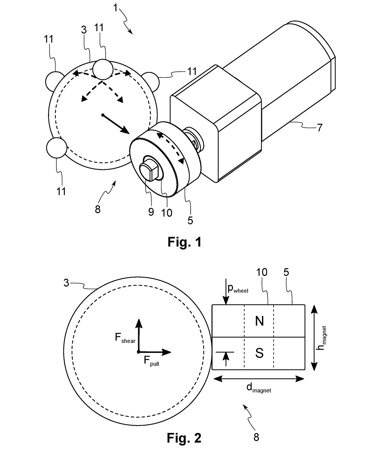
[0039]FIG. 1 schematically illustrates a magnet-assisted ball drive entity or mechanism 1, which in this example is placed inside a handheld robot. According to this example, the drive entity 1 comprises a substantially spherical element, referred to as a ball wheel 3 or simply a ball, a drive element 5, refe...


PUM


Abstract

The present invention concerns a magnet-assisted ball drive. The drive comprises a ball and a drive element in contact with the ball. The drive element is arranged to be rotated around its axis of rotation to drive the ball. The ball and the drive element each comprise magnetic material such that at least one of the ball and the drive element comprises a magnet to generate a magnetic pulling force to pull the ball and the drive element against each other.

Description

TECHNICAL FIELD[0001]The present invention relates to a magnet-assisted ball drive, which may be used for instance in robotic applications. More specifically, the proposed magnet-assisted ball drive comprises a ball driven by a drive element, where the ball and the drive element are magnetically held in contact with each other.BACKGROUND OF THE INVENTION[0002]Locomotion systems can be used in various applications, such as robotics. Aspects relating to locomotion in robotics are concerned with designing powered mechanisms that allow robots to move in their environments. The present description focuses on terrestrial locomotion, which is concerned with moving on land upon rigid structures (such as the tops of desks and tables or the ground) and is distinct from aerial, aquatic or other types of locomotion. From another perspective, locomotion can be divided into indoor and outdoor applications, which usually impose distinct requirements on the locomotion system that is built. These in...

Claims


Application Information

Patent Timeline
IPC IPC(8): B60K17/04B60B19/14B60B19/00B60K7/00
CPCB60K17/043B60B19/14B60B19/003B60K7/0007B60B2900/931B60Y2200/40B60K2007/0046B60K2007/0061
Inventor OZGUR, AYBERKLEMAIGNAN, SEVERINJOHAL, WAFAMONDADA, FRANCESCODILLENBOURG, PIERRE
Owner ECOLE POLYTECHNIQUE FEDERALE DE LAUSANNE (EPFL)
Why Eureka
Try Eureka